
Table of contents

How to make a process map: A step-by-step guide
Understand process mapping basics.
Let's kick things off with a simple truth: even the most straightforward processes can benefit from a bit of visual clarity.
Think about something as routine as making a sandwich. Easy, right? But break it down into steps, and you might discover more efficient ways to get it done—like gathering all your ingredients at once instead of making multiple trips to the pantry.
That's where process mapping shines. It's a visual tool that helps you see your current processes and uncover areas for optimization. Whether you're streamlining workflows, identifying bottlenecks, or enhancing team collaboration, a clear process map can be a game-changer for your product team.
A process map provides a detailed visual representation of each step involved in a workflow, making it easier to understand, analyze, and improve the process. By visualizing the flow of tasks, decision points, and interactions, you can quickly spot inefficiencies and areas for improvement. This can lead to significant gains in productivity and efficiency, ensuring that your team operates at its best.
Define the scope and objectives of your process map
Before diving into creating your process map, it's crucial to determine the scope and objectives. This sets the foundation for a successful mapping session.
Identify the process
Start by pinpointing the specific process you want to map. It could be anything from a user journey to an internal workflow.
Consider processes that significantly impact your team's productivity or those that frequently encounter issues. These are prime candidates for process mapping. By focusing on high-impact processes, you can ensure that your efforts will yield meaningful improvements. Gather input from your team to identify pain points and areas that could benefit from a more structured approach.
Set clear goals
What do you hope to achieve? Are you looking to identify inefficiencies, improve collaboration, or streamline operations? Clear objectives will guide your mapping efforts.
Define specific, measurable goals for your process mapping project. For example, you could reduce the time required to complete a task by 20%, eliminate unnecessary steps, or improve communication between departments. Having well-defined goals will help you stay focused and measure the success of your process improvements. Communicate these goals to your team to ensure everyone is aligned and understands the purpose of the process mapping exercise.
Gather your team
Process mapping is a collaborative activity. Bring together stakeholders from different departments to ensure you have a comprehensive view of the process.
Assemble a diverse team of people directly involved in or affected by the process you're mapping. This might include product managers, designers, engineers, and other key stakeholders. Each team member brings a unique perspective, crucial for creating an accurate and effective process map. Encourage open communication and collaboration to ensure all viewpoints are considered. This collaborative approach enhances the quality of your process map and fosters a sense of ownership and commitment among team members.
Collect necessary data
Gather all relevant information and documents related to the process. This might include existing workflows, performance data, and feedback from team members.
Before you begin mapping:
Conduct a thorough analysis of the current process.
Review any existing documentation, performance metrics, and feedback from team members.
Identify areas where the process breaks down or where improvements are needed.
Collecting comprehensive data will provide a solid foundation for your process map and help you make informed decisions. Use surveys, interviews, and observation to gather insights from those directly involved in the process. This data-driven approach ensures that your process map is based on real-world conditions and challenges.
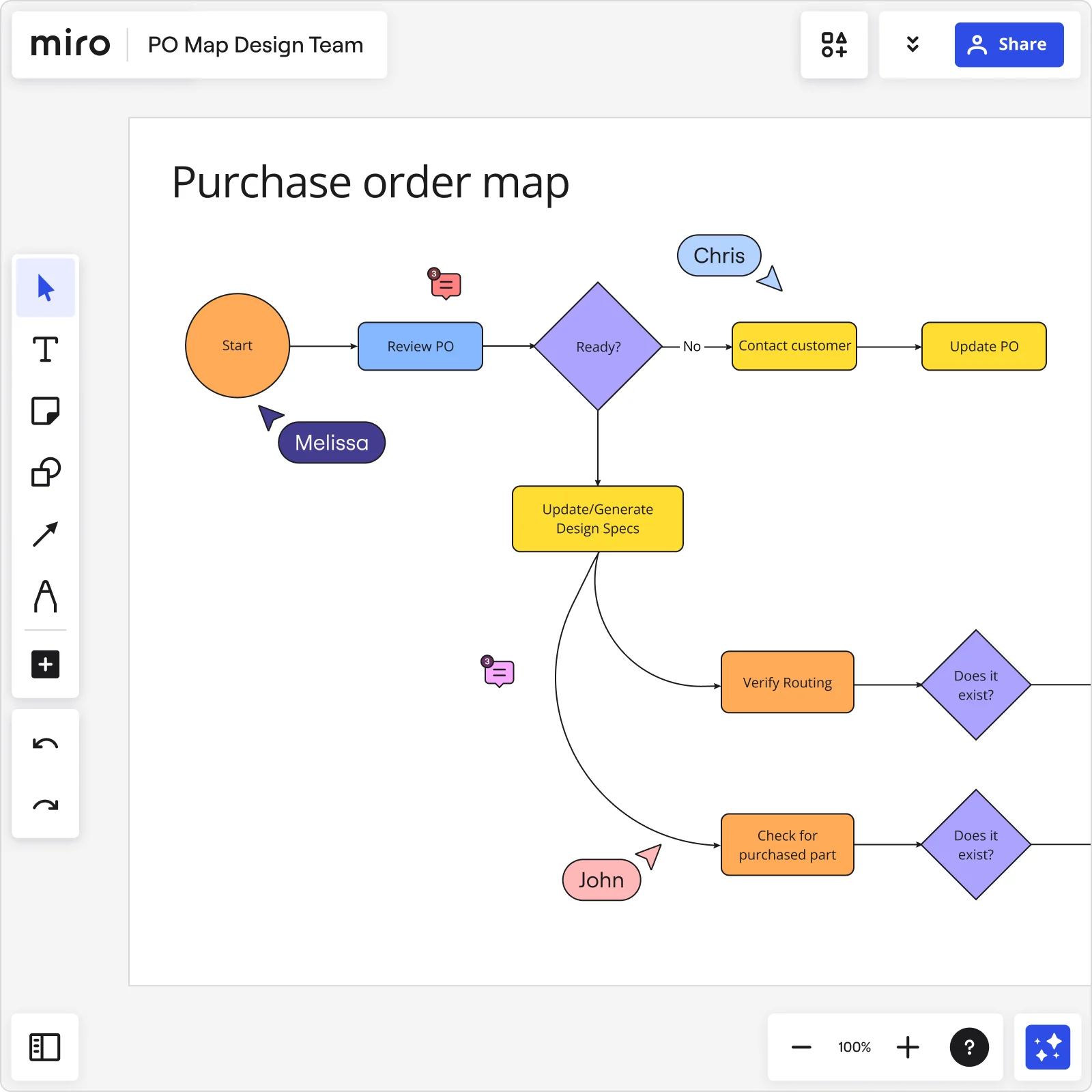
Process mapping step by step in Miro
Creating a process map in Miro is straightforward, thanks to our robust visual workspace for innovation. Here's how to get started:
1. Define your process steps
List out each step involved in your process. Use Miro's advanced diagramming shapes pack to add clarity and detail. For instance, use rectangles for tasks, diamonds for decision points, and arrows to indicate flow.
Break down the process into individual steps, focusing on tasks, decision points, and interactions. Use clear, descriptive labels for each step to ensure everyone understands the process.
Miro's advanced diagramming shapes pack provides a broad selection of options for creating detailed diagrams:
Rectangles can be used to represent tasks.
Diamonds indicate decision points.
Arrows show the flow of the process, ensuring logical connections between each step.
2. Map out decision points
Complex decision points can be challenging, so it is important to clearly delineate paths and potential outcomes. This ensures that everyone understands the potential directions a process can take based on different variables.
Decision points are critical junctures in your process where different paths may be taken based on specific criteria. Clearly mapping out these points is essential for understanding how decisions impact the overall process.
Use Miro's advanced diagramming capabilities to create detailed decision trees, showing all possible outcomes and their implications. This helps identify potential bottlenecks and ensures that everyone understands the decision-making process.
Incorporate color-coding or other visual cues to differentiate between various paths and outcomes, making the map more intuitive and easier to follow.
3. Identify bottlenecks and inefficiencies
Look for areas where tasks are repeated, issues escalate, or single points of failure exist.
Once you have mapped out the process, review it carefully to identify bottlenecks and inefficiencies. These are points in the process where tasks are delayed, repeated, or where issues tend to escalate.
Use Miro's visual workspace to highlight these areas, making them easy to spot. Miro AI can assist by analyzing your map and suggesting optimizations. For example, it might identify steps that can be combined or streamlined or highlight areas where automation could improve efficiency. By addressing these bottlenecks, you can significantly enhance the overall performance of your process.
4. Integrate feedback seamlessly
Collaboration is key. Invite your team to review the process map directly on your Miro board.
Effective process mapping requires input from all stakeholders. Use Miro's collaboration features to invite your team to review the process map. They can add comments, suggest changes, and provide feedback in real time. This ensures that all perspectives are considered and that the final process map reflects the collective knowledge and experience of the team.
5. Refine and finalize your map
Incorporate the feedback and make necessary adjustments. After gathering feedback, it's time to refine and finalize your process map. Incorporate the suggestions and make any necessary adjustments.
Miro's advanced diagramming capabilities make this process straightforward. You can easily shift parts of the process, add new steps, or remove obsolete ones. This flexibility ensures that your process map remains accurate and up-to-date. Use version control features to track changes and maintain a history of revisions. Once finalized, your process map should provide a clear, comprehensive view of the workflow, ready to guide your team toward greater efficiency and effectiveness.
6. Save and share
Once your process map is complete, save it and share it with your team.
Miro's cloud-based platform ensures that everyone on your team has access to the latest version, no matter where they are. Use the sharing options to distribute the map to all relevant stakeholders. For easy distribution, you can also export the map in various formats, such as PDF or image files. Regularly review and update the map to reflect any changes or improvements. By keeping the process map accessible and up-to-date, you ensure that it remains a valuable tool for ongoing process management and optimization.
What's next? Implement and monitor the process
Your process map is more than just a diagram—it's a roadmap for success. Here's how to make the most of it:
1. Implement changes
Begin by prioritizing the changes that will have the most significant impact. Assign responsibilities to team members and set clear timelines for implementation. Use Miro to track progress and document any challenges or adjustments needed. Regular updates to the process map ensure that it remains a living document, reflecting the current state of the process. This ongoing documentation helps maintain alignment and provides a clear record of improvements and changes.
2. Monitor performance
Establish key performance indicators (KPIs) to measure the effectiveness of the implemented changes. Regularly review these metrics to assess the impact on efficiency, productivity, and overall performance. This continuous monitoring helps ensure that the process remains optimized and that any emerging issues are promptly addressed.
3. Scale and adapt
Growth often brings new challenges and opportunities. Add new steps, integrate new tools, and adjust workflows to accommodate changing requirements. Miro's flexible platform ensures that your process maps can grow with your organization, providing a scalable solution for ongoing process management. Regularly revisit and refine your process maps to ensure they continue to meet the needs of your team and organization.
4. Foster continuous collaboration
Effective process management is an ongoing effort that requires continuous collaboration. Encourage your team to regularly review the process map and provide feedback. Miro's collaboration features make it easy for team members to share their insights and contribute to the process map. This continuous feedback loop ensures the process map remains dynamic and relevant, reflecting the latest insights and improvements. Foster a culture of continuous improvement by regularly discussing process enhancements in team meetings and making collaboration a core part of your process management strategy.
Map processes with confidence
Process mapping is a powerful way to visualize and improve workflows, identify bottlenecks, and enhance collaboration within your product team. Creating and maintaining process maps becomes a breeze with Miro's advanced diagramming capabilities and seamless integration features.
Ready to transform your processes? Explore Miro's visual workspace for innovation and take your process mapping to the next level. Happy mapping!
What is process mapping?
Process mapping, production workflow template, process mapping examples, join our 70m+ users today, plans and pricing.

7 Process Visualization Use Cases: Your Complete Manual

Key takeaways
- Process visualizations simplifies understanding and communicating complex workflows.
- Process visualization diagrams cater to different analytical needs and use cases.
- Effective application of visuals can streamline operations and facilitate team collaboration.
Process visualization is an essential tool that empowers you to understand complex processes within an organization.
By transforming text and numbers into visual diagrams, it provides a clear and immediate understanding of workflows, identifying bottlenecks, inefficiencies, or opportunities for improvement.
Whether you’re planning a new project or refining existing operations, using visuals can simplify the task at hand and make communication more effective across teams.
Visualizations come in various forms, each serving specific functions in the process analysis . Flowcharts, swimlane diagrams, and Gantt charts are just a few examples of how intricate processes can be represented visually, making them accessible and actionable.
These diagrams can serve multiple use cases, such as streamlining operations, enhancing team collaboration, or facilitating decision-making processes. With the right visualization techniques, your ability to oversee and improve processes is significantly enhanced.
What is Process Visualization?
When you’re looking to streamline your workflow or improve your operations, process visualization can be a powerful tool. It turns complex data and activities into visual formats that are easier to understand and manage.
Definition of Process Visualization
Process visualization is the graphical representation of a process or system’s workflow. It’s a technique that transforms your activities, systems, data, and operations into visual elements like diagrams and charts.
By doing so, it allows you to grasp complex processes quickly and identify areas in need of improvement.
Process maps are visual representations of the stuff your company does. A process map can represent software development, product manufacturing, IT infrastructure, employee onboarding, and more. Source: Lucidchart
Importance of Visualization in Processes
Visualization is key to improving communication and decision-making within your business.
A clear visualization aids in bridging language barriers, simplifies training, and ensures compliance with standards.
It also helps stakeholders to align on the workflow and objectives, fostering a better understanding of the full customer journey and internal processes.
Types of Process Visualizations
Various types of process visualizations are utilized depending on the specific needs and aspects of your operations:
- Flowcharts: A basic form of visualization that outlines the sequence of steps in a process.
- Process Maps: Offer a more detailed view, often including roles, decision points, and interactions.
- Customer Journey Maps: Visualize the experience and actions of a customer interacting with your company.
- BPMN Diagrams : Business Process Model and Notation diagrams that provide a standardized method for modeling.
- UML Diagrams: Universal Modeling Language diagrams used primarily in software development.
- Swimlane Diagrams: Diagrams that assign each process step to the person or team responsible.
- Gantt Charts: Useful in project management to display the timing of tasks.
- SIPOC Diagrams: Show Suppliers, Inputs, Process, Outputs, and Customers for a process.
Example of a flowchart in Microsoft Visio

Comparing Diagrams and Charts
Choosing the right visualization often involves a comparison of different diagram types. For instance:
- Flowcharts vs. Process Maps : While both display the workflow, process maps provide deeper insights into the details and interactions between different steps.
- Gantt Charts vs. Swimlane Diagrams : Gantt charts excel in showing project timelines, while swimlane diagrams are better for clarifying responsibilities.
Deciding which technique to use depends on the aspect of the process you’re focusing on—be it timing, responsibilities, decision points, or the flow of data.
Use Cases and Applications of Process Visualizations
When you explore the potential of process visualization, you’ll find its applications span across several fields, enabling clearer analysis and collaboration amongst teams.
From streamlining complex workflows to enhancing communication between stakeholders, let’s dive into some of the specific areas where these techniques shine.
1. Business Process Management (BPM)
In Business Process Management (BPM) , you can utilize tools like BPMN to map out your business process models. This aids in identifying inefficiencies and streamlining operations. Process mining techniques can extract information from event logs to give you insights into process performance.
Business Process Management (BPM) is all about optimizing the efficiency and effectiveness of the operational workflows within an organization.
- Streamlining Workflows : Visualizing business processes helps identify redundancies and bottlenecks, enabling organizations to streamline operations for better efficiency.
- Compliance and Standardization : BPM often requires adherence to certain standards and regulations. Process visualization ensures that all steps comply with the necessary guidelines and that best practices are followed consistently.
- Performance Monitoring : By creating a visual representation of workflows, managers can monitor process performance in real-time and make adjustments as needed to improve outcomes.
- Enhancing Collaboration : Process visualization in BPM fosters a shared understanding among team members, enhancing collaboration and ensuring that everyone is aligned with the process goals.
2. Human Resources (HR) Processes
Human Resources (HR) Processes benefit greatly from process visualization. Workflow diagrams help HR teams manage and optimize recruitment, onboarding, and employee development processes, ensuring that team members collaborate effectively.
In Human Resources (HR), process visualization can play a critical role in managing the various functions of the department.
- Recruitment and Onboarding : Visualizing the recruitment process helps HR to manage the various stages of hiring efficiently, from initial candidate screening to onboarding new employees.
- Employee Development : By mapping out career progression and development plans, HR can better guide employees on their growth paths within the organization.
- Performance Management : Visualizing performance review processes ensures fair and consistent evaluations, helping to identify areas for employee improvement and recognition.
- Policy Implementation : HR policies can be complex, and visualizing these processes helps ensure that they are implemented correctly and understood by all stakeholders.
3. Customer Experience and Journey Mapping
For Customer Experience and Journey Mapping , diagrams like customer journey maps turn abstract interactions into tangible visuals, allowing you to trace the customer’s pathway and improve their overall experience with data-driven decisions .

Customer experience is at the heart of any successful business, and journey mapping is a powerful way to visualize the entire customer experience process.
- Identifying Pain Points : By visualizing the customer journey, businesses can identify where customers may encounter issues or frustration, allowing for targeted improvements.
- Improving Conversion Rates : Understanding the paths that lead to conversions can help businesses refine their marketing strategies and sales funnels to improve overall conversion rates.
- Personalization : Mapping the customer journey allows for a more personalized experience, as businesses can tailor their interactions based on the specific needs and behaviors at different journey stages.
- Enhancing Customer Satisfaction : A visual map of the customer journey helps ensure that all touchpoints are designed to provide a positive experience, leading to increased customer satisfaction and loyalty.
4. Software Development and IT
In Software Development and IT , detailed UML diagrams and data flow diagrams clarify complex software architectures and processes. These visuals aid development teams in understanding requirements and dependencies, thus streamlining software creation.
In the world of software development and IT, process visualization is key to managing complex projects and ensuring efficient, high-quality outcomes.
- Agile Workflow Visualization : Visualizing the stages of Agile methodologies, like Scrum or Kanban, helps teams stay on track with development cycles and manage tasks more effectively.
- Bug Tracking : A visual representation of bug reports and their statuses can help prioritize issues and streamline the debugging process.
- System Architecture Mapping : Visual diagrams of system architectures can help IT professionals understand the interactions between different components and manage system complexity.
- Change Management : When IT systems need to undergo changes, visualizing the process can help manage the transition smoothly, ensuring minimal disruption to services.
5. Operations and Production
For Operations and Production , particularly in sectors like automotive, process visualization is essential. It helps in the meticulous process planning and design necessary to maintain efficiency and quality in high-volume environments.
In the realm of operations and production, process visualization is crucial for managing complex systems and ensuring product quality and efficiency.
- Workflow Optimization : By mapping out production workflows, businesses can identify inefficiencies and optimize for speed and waste reduction.
- Quality Control : Visualizing quality checkpoints and feedback loops helps maintain high standards and reduces the likelihood of defects.
- Inventory Management : A visual representation of inventory levels and supply chain processes can help prevent overstocking or stockouts, leading to better inventory control.
- Safety Procedures : Clearly outlined safety procedures through visual aids can improve adherence to safety protocols and reduce workplace accidents.
6. Sales and Marketing Strategies
Sales and Marketing Strategies leverage process visuals to track customer journeys and marketing funnel progress. These visuals foster better understanding and coordination of marketing efforts and sales approaches.

For sales and marketing, process visualization offers a way to strategize, track, and optimize efforts for maximum impact.
- Lead Generation and Nurturing : Visualizing the lead generation and nurturing process helps sales and marketing teams understand the customer lifecycle and tailor their approach accordingly.
- Campaign Management : Mapping out marketing campaigns provides a clear overview of all activities and timelines, ensuring that each component is executed properly and on schedule.
- Performance Tracking : Visual dashboards displaying sales and marketing metrics allow teams to monitor performance in real-time and adjust strategies as needed.
- Market Analysis : Using visual tools to analyze market trends and consumer behavior can guide more informed decision-making and strategic planning.
7. Knowledge Management and Workshops
Lastly, in Knowledge Management and Workshops , the use of visuals aids in the generation and dissemination of ideas. Teams use collaborative diagrams to capture knowledge, share insights, and drive innovation in interactive settings.
Process visualization can be a powerful ally in this domain.
- Information Retention : Visual aids can help individuals better retain and recall information by presenting it in a more engaging and digestible format.
- Complex Concept Simplification : By breaking down complex ideas into visual diagrams or flowcharts, organizations can facilitate easier understanding among employees.
- Encouraging Knowledge Sharing : Interactive visual platforms can encourage employees to contribute their expertise, fostering a collaborative knowledge-sharing culture.
- Training and Development : Visual tools can enhance training programs by illustrating procedures and best practices, making learning more effective for new and existing employees.
Workshops are designed to be collaborative and interactive, and process visualization can significantly enhance their effectiveness.
- Idea Generation : Visual brainstorming tools can help participants better articulate and develop their ideas during workshops.
- Group Collaboration : Visualizing thoughts and workflows can help align group members, ensuring everyone is on the same page and working towards a common goal.
- Actionable Outcomes : By visually mapping out the steps needed to achieve workshop goals, participants can leave with a clear action plan.
- Feedback Visualization : Gathering and displaying feedback visually can help workshop facilitators and participants identify common themes and areas for improvement.
By integrating these visualization techniques into your operations across these various domains, you’ll facilitate better communication, enhance understanding, and streamline your workflows.
Techniques and Methodologies to Visualize Processes
In your endeavors to enhance workflow efficiency, you’ll come across various techniques and methodologies for process visualization. They are the backbone of how you analyze, understand, and improve your processes. Let’s dive into some specific strategies that you can use.
Process Mapping Techniques
Creating a process map is the first step in visualizing your work processes. This visual representation is done using different techniques which include:
- Linear Process Maps: These illustrate the sequence of steps as they occur in a process.
- Cross-Functional Process Maps: These highlight the interactions between different teams or systems .
- Value Stream Mapping (VSM): VSM identifies inefficiencies and visualizes the flow from start to finish focusing on value creation.
Each technique serves the purpose of identifying critical elements such as bottlenecks and areas for process improvement .
Analysis and Improvement Methods
After process mapping , the next steps are:
- Process Analysis: It involves a thorough review of the process flows to spot inefficiencies and areas to standardize.
- Continuous Process Improvement: You will iteratively refine your processes to enhance efficiency and productivity.
Your team ‘s collaborative efforts in analysis and implementing improvements are vital for successful outcomes.
Documentation and Standardization
Documentation is key for:
- Process Standardization: Ensuring everyone adheres to the best practice
- Record Keeping: Maintaining a clear and updated description of processes
Proper process documentation ensures consistency and provides a foundation for training and knowledge transfer within your team.
Risk Assessment and Compliance
Employ process risk assessment techniques to:
- Evaluate potential risks within your process flows
- Ensure compliance with legal and industry standards
This step is crucial in protecting your organization from unforeseen threats and maintaining operational integrity.
Process Mining
Process mining is a bridge between data mining and business process management. It’s a method that uses specialized algorithms to analyze event logs recorded by an organization’s IT systems.
These logs contain the digital footprints of various business processes, capturing events like the start and end of a task, the user performing it, and the timestamp of each action.
Here’s what process mining involves and how it can be beneficial:
- Discover : Process mining software reconstructs the actual processes in real time by piecing together the sequence of events from start to finish. This can help you discover the most common pathways through a process and identify unexpected behavior.
- Enhance : By visualizing the flow of processes, you can pinpoint bottlenecks, redundancies, and deviations from the intended process flow. This information is invaluable for enhancing efficiency and compliance with standards or regulations.
- Optimize : With the insights gained from process mining, organizations can optimize their processes by eliminating inefficiencies and standardizing best practices across the board.

Image source: Celonis Process Mining
Visual Tools and Software
When you’re looking to visualize your business processes effectively, selecting the right tools is crucial. These software solutions can help you create flowcharts, facilitate team collaboration, and automate your process designs for improved productivity.
Diagramming and Mapping Tools
Lucidchart is a popular choice for creating diagrams and process maps . It allows you to visualize sequences and relationships within your business processes accurately.
You can draft detailed flowcharts to outline procedures, making complex data and workflows easier to comprehend and communicate.
Example of a flowchart in Lucidcharts

Collaboration and Productivity Platforms
For visual collaboration and productivity, platforms such as Miro and ClickUp offer versatile spaces to work together with your team.
These tools enable real-time collaboration on visual elements, helping to align team members on process planning and design.

Simulation and Modeling Software
Simulation and modeling software take your process visualization a step further. They not only depict the steps but also allow you to run hypothetical scenarios and predict outcomes.
This hands-on approach to process visualization aids in optimizing and refining your workflows before implementation.
Automation and Process Design Tools
Integrating automation into your process design can save you time and reduce errors. Tools like Zapier Canvas allow for automated process visualization , turning repetitive tasks into automated sequences.
This can streamline how your processes are visualized, designed, and executed, elevating your business’s efficiency.
Case Studies and Real-World Examples of Process Visualization
In the dynamic world of business, leveraging process visualization has proven pivotal in enhancing efficiency and compliance across various industries. Each sector, from healthcare to financial services, faces unique challenges and employs process visualization to meet these head-on.
Healthcare Process Optimization
In healthcare, you can see a transformation when process visualization aids in patient flow optimization . Imagine reducing wait times and improving patient care by identifying bottlenecks within emergency departments.

By visualizing patient pathways, healthcare providers can pinpoint problem areas fast and implement targeted process improvements to ensure a smoother customer journey through the care cycle.
Retail Workflow Streamlining
Retailers have harnessed process visualization to streamline workflows and enhance the customer shopping experience.
By mapping out the entire retail operations, from inventory management to point-of-sale interactions, you can identify delays that frustrate customers and act swiftly to rectify them. The result? A more efficient retail workflow that directly translates to happier customers and potentially higher sales.
Manufacturing Efficiency Enhancements
In manufacturing, the pressure to maintain operational efficiency while minimizing costs is constant. Through process visualization, uncovering inefficiencies in the production line becomes significantly easier.
You’re enabled to take swift action, applying automation where necessary to enhance the process flow and maintain a competitive edge with continuous manufacturing efficiency .
Financial Process Compliance
In the financial sector, adhering to compliance regimens is not just good practice—it’s the law. By visualizing processes, financial institutions can oversee and audit complex compliance procedures , ensuring no step is missed.
Better yet, this level of clarity supports improved decision-making, leading to more robust operations that can adapt to legislative changes more effectively.

Visualize and Gain Insights From Processes: The Essentials
Process visualization is more than just a set of tools—it’s a transformative approach that can illuminate the inner workings of various aspects of your business.
From enhancing customer experiences to streamlining software development, from optimizing operations to strategizing sales and marketing efforts, and from enriching knowledge management to facilitating productive workshops, the applications are as diverse as they are impactful.
Key Takeaways: Use Cases For Process Vizualizations
Key takeaways of process visualization use cases include:
- Enhanced Clarity : Visualizing processes makes complex data and workflows easier to understand at a glance, leading to better communication and decision-making.
- Improved Efficiency : By identifying bottlenecks and redundancies, process visualization helps streamline workflows, saving time and resources.
- Data-Driven Decisions : Visual tools provide a factual basis for analysis, ensuring that decisions are informed by data rather than intuition.
- Operational Excellence : In operations and production, visualization can lead to improved safety, quality control, and inventory management.
- Knowledge Sharing : Process visualization in knowledge management promotes a culture of shared understanding and continuous learning.
Remember, the power of process visualization lies in its ability to turn abstract data into tangible insights, fostering an environment where continuous improvement is not just a goal but a reality.
FAQ: Visualize Processes Use Cases
How does process visualization improve decision-making in business.
Process visualization aids decision-making by providing a clear representation of work processes, which helps in identifying inefficiencies and making informed improvements. It’s a strategic tool that facilitates a comprehensive understanding of workflows, resources, and potential bottlenecks.
What are the key benefits of using process visualization in project management?
Using process visualization in project management enhances transparency, improves communication among team members, and allows for more effective coordination. It helps you better manage timelines and resource allocation, leading to more successful project outcomes.
What tools are commonly used for visualizing complex processes?
There are various tools for visualizing complex processes, such as flowcharts, Gantt charts, and specialized software like BPM (Business Process Management) platforms. These tools streamline the creation and analysis of detailed process diagrams.
How can process mapping techniques improve operational efficiency?
Process mapping techniques provide a framework for analyzing and optimizing each step within a business process. By clearly outlining tasks and sequences, they make inefficiencies more apparent, thus paving the way for streamlining and improving overall operational efficiency.
In what ways can outcome visualization affect project outcomes?
Outcome visualization sets clear expectations by depicting the desired end state or results of a project. This visual approach aligns all stakeholders on objectives and can motivate and guide teams towards achieving set goals, positively impacting project outcomes.
Can you highlight best practices for effectively mapping business processes?
When mapping business processes, it’s best to start with a clear objective, involve cross-functional teams, use standardized symbols and notations, and regularly update the maps as processes evolve. This ensures that the maps remain accurate tools for analysis and communication.

Meet Eric, the data "guru" behind Datarundown. When he's not crunching numbers, you can find him running marathons, playing video games, and trying to win the Fantasy Premier League using his predictions model (not going so well).
Eric passionate about helping businesses make sense of their data and turning it into actionable insights. Follow along on Datarundown for all the latest insights and analysis from the data world.
Related Posts

Exploring The Benefits of Process Mining Tools

Process Mining as a Service (PROMaaS): Your Complete Manual

9 Hands-On Business Use Cases For Process Mining
- Product overview
- All features
- Latest feature release
- App integrations
CAPABILITIES
- project icon Project management
- Project views
- Custom fields
- Status updates
- goal icon Goals and reporting
- Reporting dashboards
- workflow icon Workflows and automation
- portfolio icon Resource management
- Capacity planning
- Time tracking
- my-task icon Admin and security
- Admin console
- asana-intelligence icon Asana AI
- list icon Personal
- premium icon Starter
- briefcase icon Advanced
- Goal management
- Organizational planning
- Campaign management
- Creative production
- Content calendars
- Marketing strategic planning
- Resource planning
- Project intake
- Product launches
- Employee onboarding
- View all uses arrow-right icon
- Project plans
- Team goals & objectives
- Team continuity
- Meeting agenda
- View all templates arrow-right icon
- Work management resources Discover best practices, watch webinars, get insights
- Customer stories See how the world's best organizations drive work innovation with Asana
- Help Center Get lots of tips, tricks, and advice to get the most from Asana
- Asana Academy Sign up for interactive courses and webinars to learn Asana
- Developers Learn more about building apps on the Asana platform
- Community programs Connect with and learn from Asana customers around the world
- Events Find out about upcoming events near you
- Partners Learn more about our partner programs
- Support Need help? Contact the Asana support team
- Asana for nonprofits Get more information on our nonprofit discount program, and apply.
Featured Reads

- Project management |
- Workflow diagram: Symbols, uses, and ex ...
Workflow diagram: Symbols, uses, and examples

A workflow diagram provides a visual overview of a business process or system. These diagrams help team members easily visualize their goals and deadlines, preventing potential bottlenecks. Find out how to create one of your own.
A workflow diagram can help prevent project deviations and bottlenecks by communicating goals and deadlines in a visual way. Whether you use a workflow diagram when onboarding new hires or to streamline use cases and testimonials, it’s a great way to visualize tasks and data flows.
From what it is to how to create one of your own, we’ve put together some of the most important facts to know about workflow diagrams and included helpful examples.
What is a workflow diagram?
A workflow diagram—also known as a workflow chart—provides a graphic overview of a business process or system. Usually, you’ll use these diagrams to visualize complex projects after you’ve completed the initial research and project planning stages.Once you’ve created a workflow diagram, you will have a detailed view of high level tasks and dependencies based on the overall project timeline and objectives.
Workflow diagram compared to other process mapping
Workflow diagrams share many aspects of other diagrams in the UML (Unified Modeling Language)—a standard language for specifying, visualizing, constructing, and documenting the artifacts of software systems. But workflow diagrams differ slightly from other process mapping and UML diagrams. Here, we compare them to some common types to show how:
Business process mapping
Workflow diagrams are closely related to business process mapping . The difference between the two is that a process map typically outlines steps in detail while a workflow diagram gives a visual representation of them. The objective of a workflow diagram is to help team members understand their tasks, objectives, and roles and responsibilities within the project at a high level.
Process flowcharts
Workflows and flowcharts are often confused. While the two terms sound similar, a workflow is just one type of flowchart . You can also use flowcharts to visualize other processes, like PERT charts and process documentation .
Activity diagrams
Activity diagrams are another type of flowchart that outline the flow of a series of activities within a system. It’s used to translate a business system’s functions into more digestible information for those who don’t understand the backend workings as much. In other words, an activity diagram is an easy way to visualize technical processes. For example, in Asana , you could draw an activity diagram to create a project as follows:
User clicks the button to create a project
New project launched
User customizes the project with different names and features
User saves the project and updates when needed
Data flow diagrams
Data flow diagrams follow the data through an operating system or process, whereas workflow diagrams follow the work itself. Instead of inputting actions, for example, in a data flow diagram you’d enter in metrics, results, or other data points that you want to portray.
When to use a workflow diagram
A workflow diagram is a visual representation of a process, either a new process you’re creating or an existing process you’re altering. For example:
A process to streamline your ecommerce customer journey.
A project to increase customer retention and satisfaction.
A process to automate and optimize manual tasks involving customer data.
A workflow diagram comes between the business process map (which you’ll create before the project starts) and business process automation (which you’ll use to optimize and streamline processes). This is because your map provides detailed process steps that stakeholders need to begin work, while a workflow diagram is a high level visual representation that can help clarify overarching goals during the process.
The components of a workflow diagram
In order to understand how a workflow diagram works, you first need to understand the components that make up a workflow. These include inputs, outputs, and transformations, which all help to communicate deliverables in as little time as possible.

Once you understand these components, you’ll be able to properly read a workflow process diagram and create one of your own. The main components of a workflow diagram include:
Inputs: An action that impacts the following step
Transformations: An input change
Outputs: The outcome after the transformation
These components are visualized by shapes and arrows, including:
Ovals: Represent the start and end points of a process.
Rectangles: Represent instructions about actions and steps.
Diamonds: Represent key decisions during the process build.
Circles: Represent a jump in actions and may indicate steps to bypass (in certain situations).
Arrows: Connectors that represent the dependency between all shapes and actions.
Together, these components instruct the reader how to follow the correct path and achieve the desired outcome.
Types of workflow diagrams
When it comes to visualizing processes, there are a few different workflow diagram formats that you can choose from. Each one offers unique advantages that can help you map out your next process. The type of diagram you choose will depend on the process you’re working on and your needs for that process.

From process flows to swimlanes, here are the four different types of workflow diagrams you can use for your workflow analysis.
1. Process flow diagram
A process flow diagram tool is the standard design for workflows. In this diagram, all components are mapped out chronologically, making it a basic visual representation of a process. This type of diagram provides a general overview of individual tasks and objectives without getting into too much detail.
Best for: Teams that want a high level visual representation of a new process that is quickly comprehended by any stakeholder or department.
2. Swimlane diagram
A swimlane diagram is also a popular workflow layout, though swimlanes differ quite significantly from process flow diagrams. A swimlane diagram breaks down your workflow into smaller flows or units. These flows are interconnected but separated to highlight interactions and possible inefficiencies. This creates visibility and offers a deeper dive into the overall process workflow.
Best for: Teams working on complex processes with many layers that are interrelated but independent.
3. Business process modeling notation (BPMN) diagram
BPMN uses uniform notations that both business and technical stakeholders can easily interpret. It is a type of unified modeling language which uses standardized symbols to communicate different steps.
BPMN diagrams focus on the information that is received internally and how that information is interpreted. This is why it's most commonly used for internal process changes that don't impact external customers.
Best for: Teams working on process improvements in different departments.
4. Supplier, input, process, output, customers (SIPOC) diagram
SIPOC is a type of swimlane diagram that focuses on analyzing multiple different parts of a workflow.
Unlike a traditional diagram that organizes data in sequential order, a SIPOC diagram prioritizes who creates and receives the process data. SIPOC focuses on how the data is being received internally as well as externally which is why it's used for processes associated with customer experience.
Best for: Teams looking to focus on how data is being received internally and externally.
How to create a workflow diagram (with example)
To create a workflow diagram, begin putting together the main components of your process. To do this, bring together your inputs, outputs, transformations, and your main process deliverables.

Map workflow components out on your diagram by using arrows, circles, rectangles, ovals, and diamonds to represent each data point.
1. Select your type of workflow
To select the workflow type that’s best for you, consider the functions needed for your process. Is it a complex process with multiple stakeholders best fit for a swimlane diagram? Or is it a relatively simple process that’s best suited for a simplistic process flow diagram?
While you can adjust your workflow as you go, it's easier to decide on the type of workflow up front. This way, you know exactly how complex or simple your workflow is.
2. Determine your start and end points
Next, determine your workflow start and end points (represented by ovals on your diagram).
To determine these points, consider when your process begins and when it ends. Is there an action that triggers the process? Likewise, is there an action or step that ends the process? These data points will help effectively communicate when the process begins and ends.
3. Gather necessary information
To gather information, connect with stakeholders to understand each piece of the process. This may include a kickoff meeting with various departments and leaders to gather the details and approvals needed to begin constructing your workflow diagram.
Since each process differs, the information you need to gather will also vary. Consider the steps required to complete the process, the stakeholders who will be involved, and any other significant details that will help inform readers.
4. Eliminate inefficiencies
The final step before constructing your visual workflow is to consider and eliminate any inefficiencies that may arise. Make sure you analyze inefficiencies before designing your workflow so you can prevent any issues—rather than dealing with them in real time. The specific inefficiencies will vary, but they can include a lack of resources, issues with product development, or any other obstacle that could arise during the process.
Document these inefficiencies in a change log under your change control process . This way you will be able to communicate these problems to stakeholders, prioritize inefficiencies, and track whether they've been resolved.
5. Design your workflow
Finally, begin constructing your workflow. Gather the unit information, data points, and efficiencies and map them on the diagram you chose in step one. Since each process is different and each diagram is constructed differently, yours will likely be unique in its design. Here’s just one example of what a workflow diagram might look like:

Once your workflow is designed, review it with your stakeholders to ensure it's accurate and appropriate for the situation. This is a great way to ensure all inefficiencies have been accounted for and resources have been specified properly.
Use workflows to map out processes
Visualizing workflows can help you effectively communicate deliverables to stakeholders and leadership. Plus, it’s a great way to align multiple different departments on a given process.
To take your workflows one step further, try workflow management software. From task automation to streamlined communication, Asana can help.
Related resources

Provider onboarding software: Simplify your hiring process

8 steps to write an effective project status report

Inventory management software: How to control your stock

Timesheet templates: How to track team progress
We use essential cookies to make Venngage work. By clicking “Accept All Cookies”, you agree to the storing of cookies on your device to enhance site navigation, analyze site usage, and assist in our marketing efforts.
Manage Cookies
Cookies and similar technologies collect certain information about how you’re using our website. Some of them are essential, and without them you wouldn’t be able to use Venngage. But others are optional, and you get to choose whether we use them or not.
Strictly Necessary Cookies
These cookies are always on, as they’re essential for making Venngage work, and making it safe. Without these cookies, services you’ve asked for can’t be provided.
Show cookie providers
- Google Login
Functionality Cookies
These cookies help us provide enhanced functionality and personalisation, and remember your settings. They may be set by us or by third party providers.
Performance Cookies
These cookies help us analyze how many people are using Venngage, where they come from and how they're using it. If you opt out of these cookies, we can’t get feedback to make Venngage better for you and all our users.
- Google Analytics
Targeting Cookies
These cookies are set by our advertising partners to track your activity and show you relevant Venngage ads on other sites as you browse the internet.
- Google Tag Manager
- Infographics
- Daily Infographics
- Popular Templates
- Accessibility
- Graphic Design
- Graphs and Charts
- Data Visualization
- Human Resources
- Beginner Guides
Blog Graphs and Charts Process Mapping: Everything You Need to Know [+ Templates]
Process Mapping: Everything You Need to Know [+ Templates]
Written by: Jennifer Gaskin Feb 23, 2022

Process mapping is a business and management tool organizations can use to create a visual depiction of internal or external business processes. Process maps can be used to train workers, identify bottlenecks in processes and improve communications.
While process mapping may seem complicated, it’s really not. With Venngage’s Flowchart Maker , it’s easy to visualize and organize your business processes into professional, easy-to-follow process flow maps. Let’s learn more about process mapping and explore some process flowchart templates to get you started.
Click to jump ahead
What is process mapping?
What are some examples of process mapping, what are the benefits of process mapping.
- What are the types of process maps?
How can I create process maps for a business?
Process mapping faqs.
Process mapping or business process modeling is a technique used in many businesses and organizations to create a visual representation of a workflow or process.
This business process map, for example, describes the employee involuntary termination process:

Related : How to Diagram a Business Process [Process Diagramming Templates]
Process mapping can apply to individual workers, departments or the business as a whole. Because it has such varied applications, its purpose can also vary from simply helping people understand how tasks get done to the complex work of overhauling processes that aren’t as efficient as they should be.
For example, this process map visualizes the entire process of troubleshooting slow servers. The arrows and lines give IT team members a clear set of steps to follow to make sure their customers’ systems are up and running.

Instead of providing team members with specific tasks required to get their jobs done, this process map was built to visualize the proposal process. So, instead of detailed descriptions of actions an individual worker must take, it describes actions that may or may not be taken by entire teams or departments.

In addition to visualizing the steps in a process, many organizations use process mapping to better understand how different departments might interact. In this example, each box is color-coded to a department; the effect is that it’s immediately apparent which team is responsible for which tasks.

Another example is this swimlane process map that describes the customer service process as well as showing the interaction between different teams:

Some process maps will flow in a progressive manner, meaning one task is done and then another and so on. But many businesses have operations that require many individual tasks to be done simultaneously, sometimes by separate departments, though not always. As this business process map shows, it’s still possible to create an effective process flowchart when tasks must be done at the same time.

Let’s take a look at some more process map examples to help illustrate the diversity of applications this management tool has.
This simple flowchart illustrates one of the biggest benefits of process mapping for businesses, which is training and onboarding. This process flowchart shows in detail every step involved in taking the order of a restaurant customer.

Of course, process maps can get much more complicated than taking a diner’s order, as this process flowchart shows. In this case, a disciplinary process is illustrated and explained, but it could apply to any process in which a series of decisions must be made.
Interested in using process maps to make your organization better? Check out our flowchart examples designed to improve processes.

As we’ve explored, one of the major uses for process maps is to ensure consistency and quality of work. This particular example applies to a customer service help desk , but your company could use a template like this to ensure any process is standardized.
Flowcharts and process maps aren’t the only diagrams that could be useful for your business. Learn how to use some of the most popular ones.

Process maps aren’t just good for decision-making in which multiple options are possible. They can also help organizations develop new tools and procedures, as this flowchart illustrates.

The bigger the task, the more complex it’s likely to be. That’s why process mapping often covers a vast array of tasks and departments that all flow into one another until the process is complete. As this process map shows, it’s often common for tasks to be done simultaneously across the business.

Business process mapping has a host of benefits, the most common ones include:
- Insight into current processes and workflows
- Potential to identify bottlenecks and inefficiencies
- Employee training and onboarding
- Process improvement, including quality and consistency (learn more about process documentation )
- Improving communication inside and among departments
- Identifying opportunities for process automation
- Showing compliance with applicable laws and regulations (e.g. visualize HR compliance checklists )
What are types of process maps?
Depending on what you want to communicate, you can choose different types of process maps to visualize your business processes. The most common ones include:
Basic flowchart
The simplest form of a process map is a basic flowchart covering the inputs and outputs or the steps of a process, such as this example about the customer support process:

For more examples of flowcharts, check out:
- 21+ Flowchart Examples to Organize Projects and Improve Processes
- 20+ Flow Chart Templates, Design Tips and Examples
Swimlane (Cross-functional) map
A swimlane map (also called swimlane flowchart, swimlane diagram or cross-functional diagram) visualizes a process or a workflow that’s spanning across different departments.
Phases of the workflow are usually read from left to right or top to bottom, and distinct teams are displayed in rows or columns.
Here’s an example of a swimlane flowchart describing the labor contract process and how it stretches across different departments of a company:

Detailed process map
As its name suggests, a detailed process map provides a closer look at each step of the process.
This process flowchart shows a more complex customer service process, but the use of the map goes a long way toward simplifying it. It’s easy to see at a glance how information or tasks flow and which areas of the business are responsible for each one.

High-level process map
On the other hand, a high-level process map is a high-level visual representation of a process and often looks at the relationship or interactions between SIPOC (Supplier, Input, Process, Output, Customer).
This flowchart examines in more detail what SIPOC refers to:

Value stream map
A value stream map is a lean-management tool that visualizes the process of bringing a product to its customer. It often has a unique set of symbols to illustrate the flow of information:

Workflow diagram/ Workflow map
A workflow diagram or a workflow map visualizes a process in a “flow” format:

Creating a process map for your business may seem like an intimidating prospect. But by following a few simple steps, you can create a tool for visualizing and understanding how your organization works.
Step 1: Identify the process to be mapped; in some cases, the process will cross over multiple departments. If so, it’s wise to note this before you begin actually creating the map in a later step.
Step 2: Break the process down into individual steps. How detailed you need to get depends on the process at hand.
Step 3: Use a template or create your process map from scratch using Venngage. Our smart process flowchart diagrams make it simple and easy to reorder steps, add or remove steps and apply colors and fonts to enhance understanding.
Looking for more examples of flowcharts you can use for your business? Here are 20-plus examples of flowcharts to get you started.
Do you have more questions about process mapping, how it works and how it can be used in your business? I’ve got answers.
What is process mapping in operations management?
Operations management is one of the areas in business that can benefit the most from process mapping. That’s because one of this department’s most common tasks is improving how a business functions, which can be done with the visual help of a process map.
What is process mapping in Six Sigma?
There are many schools of thought in the business world that make use of process mapping; one of the most popular is Six Sigma, a process improvement method that is highly regarded in manufacturing and management. Six Sigma process maps can be quite simple, as this Lean Six Sigma (a type of Six Sigma program) process flowchart illustrates.

How is process mapping used in business?
Process mapping has many applications in business, including training and onboarding, process improvement, communication and team building and much more.
Gain valuable insights with an engaging and informative process map
Organizations big and small can benefit from the use of process maps to help them visualize what they’re doing right (and wrong), get new team members up to speed and boost internal communication, among other benefits. With Venngage’s Process Flowcharts , just a few clicks can have you on your way.
Discover popular designs
Infographic maker

Brochure maker

White paper online

Newsletter creator

Flyer maker

Timeline maker

Letterhead maker
Mind map maker

Ebook maker

Get work done right, and right-on-time with our industry leading BPM platform.
19 Best Process Mapping Tools to Visually Manage Work
In the dynamic landscape of modern businesses, optimizing workflows is crucial. Process mapping tools serve as the guiding compass, enabling organizations to visualize, streamline, and enhance their operational efficiencies.
From intricate software platforms to intuitive diagramming solutions, these tools empower teams to chart out complex processes, fostering clarity, collaboration, and continual improvement.
In this article, we will delve into the top 19 process mapping tools, exploring their functionalities and impact on driving organizational success.
We will cover:
- The list of tools
What is process mapping?
Why are process mapping tools important, features to look for in process mapping tools, process street.

Process Street offers a seamless platform for process mapping, aiding in visualizing workflows and procedures. Its intuitive interface allows step-by-step documentation, defining roles, and incorporating rich media. With its templates and collaborative features, teams can streamline operations, track progress, and improve efficiency across various industries and tasks.
Key features:
- Checklist automation: Create and automate dynamic checklists for recurring processes.
- Conditional logic : Customize workflows with conditional logic based on responses.
- Collaborative workflows: Facilitate team collaboration on tasks and processes.
- Integration capabilities: Seamlessly integrate with tons of apps and tools.
- Task assignment: Assign and track responsibilities within processes.
- Data collection: Gather and store data through forms within checklists.
- Reporting and analytics: Generate insights with analytics on process performance.
- Version control: Maintain and track versions of checklists for auditing.
- API access: Connect with other applications through APIs.
- Document storage: Attach and manage documents relevant to processes.
- Intuitive interface makes it user-friendly.
- Offers secure data handling and storage.
- It has a mobile application.
- Custom automated workflows can be made with AI .
- It has lots of premade workflow templates to choose from.
- There is no free plan.
Pricing: Process Street pricing page .

Canva simplifies process mapping by providing customizable templates, shapes, and design elements. Users can create visual process maps with ease, utilizing its drag-and-drop interface to illustrate workflows, add annotations, and integrate branding. Its collaborative features facilitate team input, making it versatile for mapping diverse procedures and workflows.
- Image library: Extensive collection of stock photos, icons, and illustrations.
- Brand kit: Stores brand assets for consistent branding.
- Social media integration: Direct sharing to social media platforms.
- Animations: Allows the creation of animated graphics and presentations.
- Print and digital designs: Supports designs for both online and print media.
- Offers various design templates for different purposes.
- Allows easy editing of elements, colors, and fonts.
- Supports sharing and teamwork on design projects.
- Provides basic features at no cost.
- Some templates lack customization options.
- There are limitations in the number of brand assets in the free version.
Pricing: Canva pricing page .

Nifty streamlines process mapping through its project management interface, enabling task breakdowns and timelines for visualizing workflows. Its collaborative boards, task dependencies, and customizable workflows empower teams to map processes, assign tasks, and track progress seamlessly. With integrations and a user-friendly layout, it aids in efficient process management.
- Task management: Create, assign, and organize tasks.
- Project milestones: Set and track project milestones.
- Collaborative workspaces: Shared spaces for team collaboration.
- Gantt charts: Visualize project timelines and dependencies.
- Team chat: Real-time communication within the platform.
- Offers a free version.
- Monitors time spent on tasks and projects.
- Syncs tasks and milestones with calendars.
- Offers pre-built templates for various project types.
- There are limited integration capabilities.
- It takes time to get team members used to it.
Pricing: Nifty pricing page .

Lucidchart is a versatile cloud-based platform known for its intuitive interface, enabling seamless creation of diagrams and visual representations. Renowned for collaborative capabilities, it facilitates team brainstorming and process mapping. Its adaptability across industries makes it a go-to choice for illustrating complex concepts and workflows.
- Shape libraries: Extensive libraries for symbols and shapes.
- Diagram creation: Tools for creating flowcharts, mind maps, org charts, etc.
- Presentation mode: Ability to present diagrams.
- Collaborative editing: Simultaneous editing by multiple users.
- Revision history: Track changes made to diagrams.
- Ability to link shapes and objects.
- Embed diagrams in websites or documents.
- Capability to work on diagrams offline.
- Ability to customize colors, fonts, and styles.
- There is an object limit in the free version.
Pricing: Lucidchart pricing page .

Miro , a collaborative online whiteboarding platform, is often used for product management. It offers visual tools for brainstorming, creating product roadmaps, and organizing user story maps. Miro enhances product development by enabling cross-functional teams to collaborate, ideate, and plan, fostering better communication and innovation in the product management process.
- Flowchart creation: Create and customize flowcharts.
- Innovation management: Keep track of ideas and documents.
- Product roadmap tools: Design project roadmaps with whiteboards.
- Project management: Use flow charts to design project management processes.
- It has a robust set of product features.
- Excellent for idea sharing.
- Supports video conferencing.
- It’s difficult to use with a trackpad.
Pricing: Miro pricing page .
MindMeister

MindMeister serves as an effective process mapping tool by offering a visual platform for brainstorming and organizing ideas. Its mind mapping capabilities enable users to outline workflows, connect processes, and illustrate relationships. Collaborative features empower teams to collectively design, refine, and visualize intricate processes for enhanced clarity and efficiency.
- Mind mapping: Creation of visual mind maps for brainstorming.
- Collaboration: Real-time collaboration for teams.
- Templates: Pre-built templates for various mind map types.
- Customizable styles: Options to customize map styles, colors, etc.
- Export/import: Capability to import/export mind maps in various formats.
- Offers the ability to present mind maps.
- Converts map items into actionable tasks.
- Adds notes and attachments to map items.
- Embeds maps in websites or documents.
- It’s not possible to increase the size of images.
Pricing: MindMeister pricing page .
Pipefy excels as a process mapping tool by offering customizable workflows within a visual interface. It enables mapping complex processes, automating tasks, and managing workflows efficiently. With its drag-and-drop system, forms, and automation, teams can visually map, optimize, and streamline their processes for improved productivity and clarity.
- Customizable workflows: Tailor processes to specific needs.
- Visual process mapping: Drag-and-drop interface for mapping workflows.
- Automation: Automate tasks and workflows.
- Forms and fields: Create customizable forms and fields.
- Task management: Track and manage tasks within processes.
- Offers pre-built templates for various workflows.
- Monitors and manages task deadlines.
- Allows users to attach and manage files within processes.
- The data analysis is poor.
- It’s not possible to create workflow approval processes.
Pricing: Pipefy pricing page .
ClickUp is a robust project management platform acclaimed for its versatility and customization. It streamlines workflows and fosters collaboration across teams. Known for its adaptability to various work styles, ClickUp offers a comprehensive solution for task management and team communication, enhancing productivity and project organization.
- Multiple views: Kanban boards, lists, calendars, and Gantt charts for varied project perspectives.
- Time tracking: Monitor time spent on tasks and projects.
- Team collaboration: Comments, mentions, and real-time collaboration on tasks.
- Goals and OKRs: Set and track objectives and key results.
- Document management: File attachments, document editing, and version control.
- Offers a wide range of features catering to diverse project manager needs.
- Allows for the creation of automated workflows, enhancing efficiency.
- Offers a free plan ideal freelancers and small businesses .
- Users have reported occasional lags or performance issues, especially with large data sets.
Pricing: ClickUp pricing page .

GitMind serves as a versatile process mapping tool, aiding in the creation of clear visual diagrams for workflows, decision trees, and organizational processes. Its user-friendly interface and collaborative features empower teams to brainstorm, plan, and structure complex processes, fostering transparency and coherence in project management and strategy development.
- Diagram creation: Tools for creating various diagram types.
- Templates: Pre-built templates for different diagramming needs.
- Customizable styles: Options to customize diagram styles, colors, etc.
- Allows simultaneous editing by multiple users.
- Offers options to share and publish diagrams.
- There are a lot of limitations in the free version.
Pricing: GitMind pricing page .
Creately empowers seamless visual collaboration, offering a dynamic platform for creating diverse diagrams and models. Renowned for its intuitive interface, it fosters team brainstorming, aiding in process mapping, flowcharting, and wireframing. With real-time collaboration, it enhances clarity and efficiency in project planning and problem-solving, elevating teamwork experiences.
- Diagram creation: Tools for creating various types of diagrams.
- Real-time collaboration: Simultaneous editing and collaboration.
- Templates: Pre-built templates for different diagram types.
- Integration: Compatibility with various apps and platforms.
- Tracks changes and versions of diagrams.
- Very affordable for different budgets.
- Allows the ability to embed diagrams in websites or documents.
- They don’t offer many tutorials on using the software.
Pricing: Creately pricing page .

Edraw stands as a versatile diagramming tool, renowned for its user-friendly interface and extensive template library. It empowers users to create a wide array of diagrams and visuals, aiding in process mapping, flowcharting, and organizational charts. Its intuitive design fosters efficient communication and visualization of complex concepts, enhancing productivity.
- Diagram creation: Tools for various types of diagrams.
- Access controls: Permissions and access settings.
- Notes and attachments: Add notes and attachments to diagrams.
- Offline access: Capability to work on diagrams offline.
- Search and filter: Search and filter capabilities within diagrams.
- Offers pre-built templates for different diagram needs.
- Has compatibility across different operating systems.
- Provides a drag-and-drop interface.
- The paid plans are a bit pricey.
- There’s no ability to combine templates.
Pricing: Edraw pricing page .
Visual Paradigm

Visual Paradigm stands as an advanced modeling tool, renowned for its comprehensive suite of modeling capabilities. It empowers users to create intricate diagrams and models, aiding in software development, system design, and business process analysis. With its intuitive interface, it fosters efficient visualization and planning of complex systems and workflows.
- Unified modeling language (UML) support: Tools for various UML diagrams.
- Diagram creation: Create diverse diagrams for software and systems.
- Business process modeling: Tools for business process analysis and modeling.
- Team collaboration: Real-time collaboration for multiple users.
- Requirement management: Capture and manage project requirements.
- Has features for Agile methodologies.
- Generates code from models and vice versa.
- Has prototyping and wireframing capabilities.
- There is no free version.
- It is not suitable for freelancers.
Pricing: Visual Paradigm pricing page .
Google Drawings
Google Drawings offers a simple yet effective platform for process mapping, enabling users to create visual diagrams and flowcharts. Its intuitive interface and basic shapes empower individuals to outline workflows, visualize processes, and illustrate relationships. Collaborative features allow team input, making it accessible for various mapping needs.
- Basic shapes: Tools for creating various shapes.
- Text editing: Capability to add and edit text.
- Lines and connectors: Tools for drawing lines and connectors.
- Image insertion: Ability to add and manipulate images.
- Color and fill options: Customizable color and fill settings.
- Has tools for freehand drawing.
- Has the capability to work with multiple layers.
- Gives users the ability to add comments and annotations.
- There are options to group and ungroup elements.
- There are no project management options.
Pricing: It’s free!
Gliffy serves as a robust process mapping tool, offering a user-friendly platform to create visual diagrams and flowcharts. Its intuitive interface and extensive shape library enable the seamless mapping of workflows, facilitating team collaboration. With its collaborative features and templates, it aids in illustrating and optimizing complex processes efficiently.
- Templates: Pre-built templates for different diagram needs.
- Customizable styles: Options to modify diagram styles, colors, etc.
- Drag-and-drop interface: Intuitive tools for easy diagram creation.
- Real-time collaboration: Simultaneous editing by multiple users.
- Capability to import/export diagrams in various formats.
- Has compatibility with various apps and platforms.
- Offers permissions and access settings.
- Provides features for managing teams and users.
- Users have to pay for each integration.
Pricing: Gliffy pricing page .

Cacoo functions as a versatile process mapping tool, providing a collaborative platform for creating visual diagrams and flowcharts. Its intuitive interface and extensive shape library empower users to map workflows, collaborate in real time, and illustrate complex processes. It facilitates team coordination and clarity in process visualization and optimization.
- Diagram embedding: Embed diagrams in websites or documents.
- Allows users to access and edit diagrams on mobile devices.
- Offers the capability to work on diagrams offline.
- Has collaboration features for comments and feedback.
- Usage is limited in certain plans.
Pricing: Cacoo pricing page .

Visme stands as a versatile visual content creation platform, offering intuitive tools to craft engaging presentations, infographics, and diagrams. Its user-friendly interface and diverse templates empower users to convey complex information effectively. Renowned for its design flexibility, it aids in creating impactful visuals for diverse communication needs.
- Presentation creation: Tools for creating interactive presentations.
- Infographic design: Features for designing infographics.
- Data visualization: Tools for presenting data visually.
- Templates: Pre-built templates for various visual content.
- Customizable designs: Options to customize styles, colors, etc.
- Has a diverse library of icons and images.
- Offers the ability to create interactive elements.
- Has tools for creating charts and graphs.
- It’s difficult to create custom measurements.
Pricing: Visme pricing page .

Draw.io functions as an intuitive and versatile diagramming tool, offering a robust platform for creating diverse diagrams and flowcharts. Renowned for its user-friendly interface and compatibility, it facilitates easy visualization and planning, aiding in illustrating complex ideas and processes effectively for various industries and tasks.
- Export/import: Capability to import/export diagrams in various formats.
- Has search and filter capabilities within diagrams.
- It lacks many features similar products have.
Google Docs
Google Docs serves as a rudimentary process mapping tool, albeit limited in visual capabilities. Its tables, shapes, and text features allow basic process mapping by creating tables for steps, inserting shapes for workflows, and organizing text to outline procedures. Collaborative editing enhances collective mapping efforts within documents.
- Text editing: Tools for creating and editing text.
- Collaborative editing: Real-time editing by multiple users.
- Formatting options: Customization of text styles, fonts, etc.
- Tables: Tools for creating and organizing tables.
- Comments and suggestions: Collaboration features for feedback.
- It costs nothing.
- It’s good for basic process mapping.
- It cannot do more than basic process mapping.
Microsoft Excel
Microsoft Excel can function as a basic process mapping tool by employing cells, tables, and shapes to outline sequential steps and workflows. Its grid structure allows the organization of processes, with cells used to detail each step, albeit lacking advanced visual mapping features. Macros and formulas enhance functional mapping capabilities.
- Cells and grid structure: Basic structure for organizing data.
- Tables and formatting: Tools for structuring data and content.
- Shapes and drawing tools: Basic shapes for visual representation.
- Formulas and functions: Mathematical functions for calculations.
- Conditional formatting: Highlighting cells based on conditions.
- Organizes and filters data.
- Controls data input with validation rules.
- Establishes relationships between cells.
- You can create graphs .
- It can only be used for basic process mapping.
- You have to subscribe to all of Microsoft 365’s suite of products to access it.
Pricing: Microsoft 365 pricing page .
Process mapping is a visual representation of how a process works, from beginning to end. It is a powerful tool used to understand and improve the flow of work in any organization, by highlighting areas of inefficiency, redundancy, or waste. Process mapping allows for a clear and concise depiction of how a process functions, making it easier to identify areas for improvement and optimization.
There are different types of detailed process maps, such as flowcharts, network diagrams, swimlane diagrams, and value stream mapping (VSM), which are used depending on the complexity and nature of the process being analyzed.
Flowcharts are the most common type of process mapping and are used to document and visualize the steps and decision points within a process. Swimlane diagrams, on the other hand, are used to show the interplay between different departments or individuals involved in a process.
Finally, value stream mapping and network diagrams are a method used to analyze and improve the flow of materials and information required to bring a product or service to a customer.
Process mapping is not only a useful tool for streamlining and improving operational processes and process documentation, but it also allows for greater understanding and communication of how work is done within an organization.
By creating a visual representation of a process, employees, managers, and stakeholders can better grasp how their work fits into the larger picture and identify where improvements can be made.
Different types of process mapping diagrams
There are several different types of process maps, each serving a specific purpose in visualizing and analyzing different aspects of a process. Some of the most common types include:
A flowchart is a visual representation of the steps and decisions in a process, using different shapes and arrows to illustrate the flow of activities.
Swimlane diagram
A swimlane diagram , also known as a cross-functional flowchart, shows the interactions between different departments, roles, or individuals involved in a process, often using lanes to denote each party’s responsibilities.
Value stream map
A value stream map focuses on understanding and improving the flow of materials and information in a specific process, with a particular emphasis on identifying non-value-added activities and reducing waste.
Business process model and notation (BPMN) diagram
BPMN diagrams use standardized symbols and notation to depict the sequence of activities, events, and decisions in a process, including the various participants and their interactions.
Gantt chart
While not exclusively a process mapping diagram, Gantt charts are often used to visualize the timeline and dependencies of tasks within a project or process, helping to plan and monitor progress effectively.
Process mapping templates and tools are important for a variety of reasons.
First and foremost, they provide a visual representation of a business or organizational process, allowing for a clear and detailed understanding of how tasks are completed and how information flows within the process. This visual representation can help to identify inefficiencies, redundancies, and bottlenecks within the process, and can be used to streamline and optimize workflow.
In addition to providing a visual representation, process mapping tools also allow for the documentation and standardization of processes. This can be incredibly valuable for businesses looking to maintain consistency and quality in their operations, as well as for those seeking to comply with industry regulations and standards. Standardized processes can also make it easier for new employees to quickly integrate into a team and understand their role within the larger context of the organization.
Process mapping tools can also facilitate communication and collaboration within an organization. By providing a clear and easily understandable representation of a process, these tools can help to align different teams and departments around shared goals and objectives, and can foster a sense of transparency and accountability within the organization.
Furthermore, process mapping tools can be used to support continuous improvement efforts within an organization. By providing a visual representation of a process, these tools can help to identify areas for improvement and encourage experimentation and innovation. This can result in a more agile and adaptable organization, better able to respond to changing market conditions and customer needs.
When choosing a process mapping software, it is important to consider the following features:
Intuitive user interface
The tool should have an easy-to-use interface that allows for drag-and-drop functionality and customizable symbols and shapes.
Collaboration capabilities
Look for a tool that allows for multiple users to work on the same process map simultaneously and offers real-time collaboration features.
Integration with other systems
Choose a tool that integrates with other software or systems, such as ERP, CRM, or BPM software for seamless data sharing and process automation.
Customization options
The tool should offer customization options for colors, styles, and templates to create professional-looking process maps.
Data visualization
Look for features that allow for data visualization, such as charts, diagrams, and graphs to represent process metrics and performance.
Version control and history tracking
The tool should provide version control and history tracking to keep track of changes made to process maps and allow for easy rollback if needed.
Security and permissions
Ensure that the tool offers security features such as role-based access control and data encryption to protect sensitive process information.
Related posts
- Business Process Management
- Process Management
- BPM Software
- Business Process Management Template
- Process Management Software
- Process Management Tools
- Process Checklist
- Definition of Process Management
- Business Operations Management Software
Take control of your workflows today
- Open access
- Published: 19 July 2015
The role of visual representations in scientific practices: from conceptual understanding and knowledge generation to ‘seeing’ how science works
- Maria Evagorou 1 ,
- Sibel Erduran 2 &
- Terhi Mäntylä 3
International Journal of STEM Education volume 2 , Article number: 11 ( 2015 ) Cite this article
76k Accesses
78 Citations
13 Altmetric
Metrics details
The use of visual representations (i.e., photographs, diagrams, models) has been part of science, and their use makes it possible for scientists to interact with and represent complex phenomena, not observable in other ways. Despite a wealth of research in science education on visual representations, the emphasis of such research has mainly been on the conceptual understanding when using visual representations and less on visual representations as epistemic objects. In this paper, we argue that by positioning visual representations as epistemic objects of scientific practices, science education can bring a renewed focus on how visualization contributes to knowledge formation in science from the learners’ perspective.
This is a theoretical paper, and in order to argue about the role of visualization, we first present a case study, that of the discovery of the structure of DNA that highlights the epistemic components of visual information in science. The second case study focuses on Faraday’s use of the lines of magnetic force. Faraday is known of his exploratory, creative, and yet systemic way of experimenting, and the visual reasoning leading to theoretical development was an inherent part of the experimentation. Third, we trace a contemporary account from science focusing on the experimental practices and how reproducibility of experimental procedures can be reinforced through video data.
Conclusions
Our conclusions suggest that in teaching science, the emphasis in visualization should shift from cognitive understanding—using the products of science to understand the content—to engaging in the processes of visualization. Furthermore, we suggest that is it essential to design curriculum materials and learning environments that create a social and epistemic context and invite students to engage in the practice of visualization as evidence, reasoning, experimental procedure, or a means of communication and reflect on these practices. Implications for teacher education include the need for teacher professional development programs to problematize the use of visual representations as epistemic objects that are part of scientific practices.
During the last decades, research and reform documents in science education across the world have been calling for an emphasis not only on the content but also on the processes of science (Bybee 2014 ; Eurydice 2012 ; Duschl and Bybee 2014 ; Osborne 2014 ; Schwartz et al. 2012 ), in order to make science accessible to the students and enable them to understand the epistemic foundation of science. Scientific practices, part of the process of science, are the cognitive and discursive activities that are targeted in science education to develop epistemic understanding and appreciation of the nature of science (Duschl et al. 2008 ) and have been the emphasis of recent reform documents in science education across the world (Achieve 2013 ; Eurydice 2012 ). With the term scientific practices, we refer to the processes that take place during scientific discoveries and include among others: asking questions, developing and using models, engaging in arguments, and constructing and communicating explanations (National Research Council 2012 ). The emphasis on scientific practices aims to move the teaching of science from knowledge to the understanding of the processes and the epistemic aspects of science. Additionally, by placing an emphasis on engaging students in scientific practices, we aim to help students acquire scientific knowledge in meaningful contexts that resemble the reality of scientific discoveries.
Despite a wealth of research in science education on visual representations, the emphasis of such research has mainly been on the conceptual understanding when using visual representations and less on visual representations as epistemic objects. In this paper, we argue that by positioning visual representations as epistemic objects, science education can bring a renewed focus on how visualization contributes to knowledge formation in science from the learners’ perspective. Specifically, the use of visual representations (i.e., photographs, diagrams, tables, charts) has been part of science and over the years has evolved with the new technologies (i.e., from drawings to advanced digital images and three dimensional models). Visualization makes it possible for scientists to interact with complex phenomena (Richards 2003 ), and they might convey important evidence not observable in other ways. Visual representations as a tool to support cognitive understanding in science have been studied extensively (i.e., Gilbert 2010 ; Wu and Shah 2004 ). Studies in science education have explored the use of images in science textbooks (i.e., Dimopoulos et al. 2003 ; Bungum 2008 ), students’ representations or models when doing science (i.e., Gilbert et al. 2008 ; Dori et al. 2003 ; Lehrer and Schauble 2012 ; Schwarz et al. 2009 ), and students’ images of science and scientists (i.e., Chambers 1983 ). Therefore, studies in the field of science education have been using the term visualization as “the formation of an internal representation from an external representation” (Gilbert et al. 2008 , p. 4) or as a tool for conceptual understanding for students.
In this paper, we do not refer to visualization as mental image, model, or presentation only (Gilbert et al. 2008 ; Philips et al. 2010 ) but instead focus on visual representations or visualization as epistemic objects. Specifically, we refer to visualization as a process for knowledge production and growth in science. In this respect, modeling is an aspect of visualization, but what we are focusing on with visualization is not on the use of model as a tool for cognitive understanding (Gilbert 2010 ; Wu and Shah 2004 ) but the on the process of modeling as a scientific practice which includes the construction and use of models, the use of other representations, the communication in the groups with the use of the visual representation, and the appreciation of the difficulties that the science phase in this process. Therefore, the purpose of this paper is to present through the history of science how visualization can be considered not only as a cognitive tool in science education but also as an epistemic object that can potentially support students to understand aspects of the nature of science.
Scientific practices and science education
According to the New Generation Science Standards (Achieve 2013 ), scientific practices refer to: asking questions and defining problems; developing and using models; planning and carrying out investigations; analyzing and interpreting data; using mathematical and computational thinking; constructing explanations and designing solutions; engaging in argument from evidence; and obtaining, evaluating, and communicating information. A significant aspect of scientific practices is that science learning is more than just about learning facts, concepts, theories, and laws. A fuller appreciation of science necessitates the understanding of the science relative to its epistemological grounding and the process that are involved in the production of knowledge (Hogan and Maglienti 2001 ; Wickman 2004 ).
The New Generation Science Standards is, among other changes, shifting away from science inquiry and towards the inclusion of scientific practices (Duschl and Bybee 2014 ; Osborne 2014 ). By comparing the abilities to do scientific inquiry (National Research Council 2000 ) with the set of scientific practices, it is evident that the latter is about engaging in the processes of doing science and experiencing in that way science in a more authentic way. Engaging in scientific practices according to Osborne ( 2014 ) “presents a more authentic picture of the endeavor that is science” (p.183) and also helps the students to develop a deeper understanding of the epistemic aspects of science. Furthermore, as Bybee ( 2014 ) argues, by engaging students in scientific practices, we involve them in an understanding of the nature of science and an understanding on the nature of scientific knowledge.
Science as a practice and scientific practices as a term emerged by the philosopher of science, Kuhn (Osborne 2014 ), refers to the processes in which the scientists engage during knowledge production and communication. The work that is followed by historians, philosophers, and sociologists of science (Latour 2011 ; Longino 2002 ; Nersessian 2008 ) revealed the scientific practices in which the scientists engage in and include among others theory development and specific ways of talking, modeling, and communicating the outcomes of science.
Visualization as an epistemic object
Schematic, pictorial symbols in the design of scientific instruments and analysis of the perceptual and functional information that is being stored in those images have been areas of investigation in philosophy of scientific experimentation (Gooding et al. 1993 ). The nature of visual perception, the relationship between thought and vision, and the role of reproducibility as a norm for experimental research form a central aspect of this domain of research in philosophy of science. For instance, Rothbart ( 1997 ) has argued that visualizations are commonplace in the theoretical sciences even if every scientific theory may not be defined by visualized models.
Visual representations (i.e., photographs, diagrams, tables, charts, models) have been used in science over the years to enable scientists to interact with complex phenomena (Richards 2003 ) and might convey important evidence not observable in other ways (Barber et al. 2006 ). Some authors (e.g., Ruivenkamp and Rip 2010 ) have argued that visualization is as a core activity of some scientific communities of practice (e.g., nanotechnology) while others (e.g., Lynch and Edgerton 1988 ) have differentiated the role of particular visualization techniques (e.g., of digital image processing in astronomy). Visualization in science includes the complex process through which scientists develop or produce imagery, schemes, and graphical representation, and therefore, what is of importance in this process is not only the result but also the methodology employed by the scientists, namely, how this result was produced. Visual representations in science may refer to objects that are believed to have some kind of material or physical existence but equally might refer to purely mental, conceptual, and abstract constructs (Pauwels 2006 ). More specifically, visual representations can be found for: (a) phenomena that are not observable with the eye (i.e., microscopic or macroscopic); (b) phenomena that do not exist as visual representations but can be translated as such (i.e., sound); and (c) in experimental settings to provide visual data representations (i.e., graphs presenting velocity of moving objects). Additionally, since science is not only about replicating reality but also about making it more understandable to people (either to the public or other scientists), visual representations are not only about reproducing the nature but also about: (a) functioning in helping solving a problem, (b) filling gaps in our knowledge, and (c) facilitating knowledge building or transfer (Lynch 2006 ).
Using or developing visual representations in the scientific practice can range from a straightforward to a complicated situation. More specifically, scientists can observe a phenomenon (i.e., mitosis) and represent it visually using a picture or diagram, which is quite straightforward. But they can also use a variety of complicated techniques (i.e., crystallography in the case of DNA studies) that are either available or need to be developed or refined in order to acquire the visual information that can be used in the process of theory development (i.e., Latour and Woolgar 1979 ). Furthermore, some visual representations need decoding, and the scientists need to learn how to read these images (i.e., radiologists); therefore, using visual representations in the process of science requires learning a new language that is specific to the medium/methods that is used (i.e., understanding an X-ray picture is different from understanding an MRI scan) and then communicating that language to other scientists and the public.
There are much intent and purposes of visual representations in scientific practices, as for example to make a diagnosis, compare, describe, and preserve for future study, verify and explore new territory, generate new data (Pauwels 2006 ), or present new methodologies. According to Latour and Woolgar ( 1979 ) and Knorr Cetina ( 1999 ), visual representations can be used either as primary data (i.e., image from a microscope). or can be used to help in concept development (i.e., models of DNA used by Watson and Crick), to uncover relationships and to make the abstract more concrete (graphs of sound waves). Therefore, visual representations and visual practices, in all forms, are an important aspect of the scientific practices in developing, clarifying, and transmitting scientific knowledge (Pauwels 2006 ).
Methods and Results: Merging Visualization and scientific practices in science
In this paper, we present three case studies that embody the working practices of scientists in an effort to present visualization as a scientific practice and present our argument about how visualization is a complex process that could include among others modeling and use of representation but is not only limited to that. The first case study explores the role of visualization in the construction of knowledge about the structure of DNA, using visuals as evidence. The second case study focuses on Faraday’s use of the lines of magnetic force and the visual reasoning leading to the theoretical development that was an inherent part of the experimentation. The third case study focuses on the current practices of scientists in the context of a peer-reviewed journal called the Journal of Visualized Experiments where the methodology is communicated through videotaped procedures. The three case studies represent the research interests of the three authors of this paper and were chosen to present how visualization as a practice can be involved in all stages of doing science, from hypothesizing and evaluating evidence (case study 1) to experimenting and reasoning (case study 2) to communicating the findings and methodology with the research community (case study 3), and represent in this way the three functions of visualization as presented by Lynch ( 2006 ). Furthermore, the last case study showcases how the development of visualization technologies has contributed to the communication of findings and methodologies in science and present in that way an aspect of current scientific practices. In all three cases, our approach is guided by the observation that the visual information is an integral part of scientific practices at the least and furthermore that they are particularly central in the scientific practices of science.
Case study 1: use visual representations as evidence in the discovery of DNA
The focus of the first case study is the discovery of the structure of DNA. The DNA was first isolated in 1869 by Friedrich Miescher, and by the late 1940s, it was known that it contained phosphate, sugar, and four nitrogen-containing chemical bases. However, no one had figured the structure of the DNA until Watson and Crick presented their model of DNA in 1953. Other than the social aspects of the discovery of the DNA, another important aspect was the role of visual evidence that led to knowledge development in the area. More specifically, by studying the personal accounts of Watson ( 1968 ) and Crick ( 1988 ) about the discovery of the structure of the DNA, the following main ideas regarding the role of visual representations in the production of knowledge can be identified: (a) The use of visual representations was an important part of knowledge growth and was often dependent upon the discovery of new technologies (i.e., better microscopes or better techniques in crystallography that would provide better visual representations as evidence of the helical structure of the DNA); and (b) Models (three-dimensional) were used as a way to represent the visual images (X-ray images) and connect them to the evidence provided by other sources to see whether the theory can be supported. Therefore, the model of DNA was built based on the combination of visual evidence and experimental data.
An example showcasing the importance of visual representations in the process of knowledge production in this case is provided by Watson, in his book The Double Helix (1968):
…since the middle of the summer Rosy [Rosalind Franklin] had had evidence for a new three-dimensional form of DNA. It occurred when the DNA 2molecules were surrounded by a large amount of water. When I asked what the pattern was like, Maurice went into the adjacent room to pick up a print of the new form they called the “B” structure. The instant I saw the picture, my mouth fell open and my pulse began to race. The pattern was unbelievably simpler than those previously obtained (A form). Moreover, the black cross of reflections which dominated the picture could arise only from a helical structure. With the A form the argument for the helix was never straightforward, and considerable ambiguity existed as to exactly which type of helical symmetry was present. With the B form however, mere inspection of its X-ray picture gave several of the vital helical parameters. (p. 167-169)
As suggested by Watson’s personal account of the discovery of the DNA, the photo taken by Rosalind Franklin (Fig. 1 ) convinced him that the DNA molecule must consist of two chains arranged in a paired helix, which resembles a spiral staircase or ladder, and on March 7, 1953, Watson and Crick finished and presented their model of the structure of DNA (Watson and Berry 2004 ; Watson 1968 ) which was based on the visual information provided by the X-ray image and their knowledge of chemistry.
X-ray chrystallography of DNA
In analyzing the visualization practice in this case study, we observe the following instances that highlight how the visual information played a role:
Asking questions and defining problems: The real world in the model of science can at some points only be observed through visual representations or representations, i.e., if we are using DNA as an example, the structure of DNA was only observable through the crystallography images produced by Rosalind Franklin in the laboratory. There was no other way to observe the structure of DNA, therefore the real world.
Analyzing and interpreting data: The images that resulted from crystallography as well as their interpretations served as the data for the scientists studying the structure of DNA.
Experimenting: The data in the form of visual information were used to predict the possible structure of the DNA.
Modeling: Based on the prediction, an actual three-dimensional model was prepared by Watson and Crick. The first model did not fit with the real world (refuted by Rosalind Franklin and her research group from King’s College) and Watson and Crick had to go through the same process again to find better visual evidence (better crystallography images) and create an improved visual model.
Example excerpts from Watson’s biography provide further evidence for how visualization practices were applied in the context of the discovery of DNA (Table 1 ).
In summary, by examining the history of the discovery of DNA, we showcased how visual data is used as scientific evidence in science, identifying in that way an aspect of the nature of science that is still unexplored in the history of science and an aspect that has been ignored in the teaching of science. Visual representations are used in many ways: as images, as models, as evidence to support or rebut a model, and as interpretations of reality.
Case study 2: applying visual reasoning in knowledge production, the example of the lines of magnetic force
The focus of this case study is on Faraday’s use of the lines of magnetic force. Faraday is known of his exploratory, creative, and yet systemic way of experimenting, and the visual reasoning leading to theoretical development was an inherent part of this experimentation (Gooding 2006 ). Faraday’s articles or notebooks do not include mathematical formulations; instead, they include images and illustrations from experimental devices and setups to the recapping of his theoretical ideas (Nersessian 2008 ). According to Gooding ( 2006 ), “Faraday’s visual method was designed not to copy apparent features of the world, but to analyse and replicate them” (2006, p. 46).
The lines of force played a central role in Faraday’s research on electricity and magnetism and in the development of his “field theory” (Faraday 1852a ; Nersessian 1984 ). Before Faraday, the experiments with iron filings around magnets were known and the term “magnetic curves” was used for the iron filing patterns and also for the geometrical constructs derived from the mathematical theory of magnetism (Gooding et al. 1993 ). However, Faraday used the lines of force for explaining his experimental observations and in constructing the theory of forces in magnetism and electricity. Examples of Faraday’s different illustrations of lines of magnetic force are given in Fig. 2 . Faraday gave the following experiment-based definition for the lines of magnetic forces:
a Iron filing pattern in case of bar magnet drawn by Faraday (Faraday 1852b , Plate IX, p. 158, Fig. 1), b Faraday’s drawing of lines of magnetic force in case of cylinder magnet, where the experimental procedure, knife blade showing the direction of lines, is combined into drawing (Faraday, 1855, vol. 1, plate 1)
A line of magnetic force may be defined as that line which is described by a very small magnetic needle, when it is so moved in either direction correspondent to its length, that the needle is constantly a tangent to the line of motion; or it is that line along which, if a transverse wire be moved in either direction, there is no tendency to the formation of any current in the wire, whilst if moved in any other direction there is such a tendency; or it is that line which coincides with the direction of the magnecrystallic axis of a crystal of bismuth, which is carried in either direction along it. The direction of these lines about and amongst magnets and electric currents, is easily represented and understood, in a general manner, by the ordinary use of iron filings. (Faraday 1852a , p. 25 (3071))
The definition describes the connection between the experiments and the visual representation of the results. Initially, the lines of force were just geometric representations, but later, Faraday treated them as physical objects (Nersessian 1984 ; Pocovi and Finlay 2002 ):
I have sometimes used the term lines of force so vaguely, as to leave the reader doubtful whether I intended it as a merely representative idea of the forces, or as the description of the path along which the power was continuously exerted. … wherever the expression line of force is taken simply to represent the disposition of forces, it shall have the fullness of that meaning; but that wherever it may seem to represent the idea of the physical mode of transmission of the force, it expresses in that respect the opinion to which I incline at present. The opinion may be erroneous, and yet all that relates or refers to the disposition of the force will remain the same. (Faraday, 1852a , p. 55-56 (3075))
He also felt that the lines of force had greater explanatory power than the dominant theory of action-at-a-distance:
Now it appears to me that these lines may be employed with great advantage to represent nature, condition, direction and comparative amount of the magnetic forces; and that in many cases they have, to the physical reasoned at least, a superiority over that method which represents the forces as concentrated in centres of action… (Faraday, 1852a , p. 26 (3074))
For giving some insight to Faraday’s visual reasoning as an epistemic practice, the following examples of Faraday’s studies of the lines of magnetic force (Faraday 1852a , 1852b ) are presented:
(a) Asking questions and defining problems: The iron filing patterns formed the empirical basis for the visual model: 2D visualization of lines of magnetic force as presented in Fig. 2 . According to Faraday, these iron filing patterns were suitable for illustrating the direction and form of the magnetic lines of force (emphasis added):
It must be well understood that these forms give no indication by their appearance of the relative strength of the magnetic force at different places, inasmuch as the appearance of the lines depends greatly upon the quantity of filings and the amount of tapping; but the direction and forms of these lines are well given, and these indicate, in a considerable degree, the direction in which the forces increase and diminish . (Faraday 1852b , p.158 (3237))
Despite being static and two dimensional on paper, the lines of magnetic force were dynamical (Nersessian 1992 , 2008 ) and three dimensional for Faraday (see Fig. 2 b). For instance, Faraday described the lines of force “expanding”, “bending,” and “being cut” (Nersessian 1992 ). In Fig. 2 b, Faraday has summarized his experiment (bar magnet and knife blade) and its results (lines of force) in one picture.
(b) Analyzing and interpreting data: The model was so powerful for Faraday that he ended up thinking them as physical objects (e.g., Nersessian 1984 ), i.e., making interpretations of the way forces act. Of course, he made a lot of experiments for showing the physical existence of the lines of force, but he did not succeed in it (Nersessian 1984 ). The following quote illuminates Faraday’s use of the lines of force in different situations:
The study of these lines has, at different times, been greatly influential in leading me to various results, which I think prove their utility as well as fertility. Thus, the law of magneto-electric induction; the earth’s inductive action; the relation of magnetism and light; diamagnetic action and its law, and magnetocrystallic action, are the cases of this kind… (Faraday 1852a , p. 55 (3174))
(c) Experimenting: In Faraday's case, he used a lot of exploratory experiments; in case of lines of magnetic force, he used, e.g., iron filings, magnetic needles, or current carrying wires (see the quote above). The magnetic field is not directly observable and the representation of lines of force was a visual model, which includes the direction, form, and magnitude of field.
(d) Modeling: There is no denying that the lines of magnetic force are visual by nature. Faraday’s views of lines of force developed gradually during the years, and he applied and developed them in different contexts such as electromagnetic, electrostatic, and magnetic induction (Nersessian 1984 ). An example of Faraday’s explanation of the effect of the wire b’s position to experiment is given in Fig. 3 . In Fig. 3 , few magnetic lines of force are drawn, and in the quote below, Faraday is explaining the effect using these magnetic lines of force (emphasis added):
Picture of an experiment with different arrangements of wires ( a , b’ , b” ), magnet, and galvanometer. Note the lines of force drawn around the magnet. (Faraday 1852a , p. 34)
It will be evident by inspection of Fig. 3 , that, however the wires are carried away, the general result will, according to the assumed principles of action, be the same; for if a be the axial wire, and b’, b”, b”’ the equatorial wire, represented in three different positions, whatever magnetic lines of force pass across the latter wire in one position, will also pass it in the other, or in any other position which can be given to it. The distance of the wire at the place of intersection with the lines of force, has been shown, by the experiments (3093.), to be unimportant. (Faraday 1852a , p. 34 (3099))
In summary, by examining the history of Faraday’s use of lines of force, we showed how visual imagery and reasoning played an important part in Faraday’s construction and representation of his “field theory”. As Gooding has stated, “many of Faraday’s sketches are far more that depictions of observation, they are tools for reasoning with and about phenomena” (2006, p. 59).
Case study 3: visualizing scientific methods, the case of a journal
The focus of the third case study is the Journal of Visualized Experiments (JoVE) , a peer-reviewed publication indexed in PubMed. The journal devoted to the publication of biological, medical, chemical, and physical research in a video format. The journal describes its history as follows:
JoVE was established as a new tool in life science publication and communication, with participation of scientists from leading research institutions. JoVE takes advantage of video technology to capture and transmit the multiple facets and intricacies of life science research. Visualization greatly facilitates the understanding and efficient reproduction of both basic and complex experimental techniques, thereby addressing two of the biggest challenges faced by today's life science research community: i) low transparency and poor reproducibility of biological experiments and ii) time and labor-intensive nature of learning new experimental techniques. ( http://www.jove.com/ )
By examining the journal content, we generate a set of categories that can be considered as indicators of relevance and significance in terms of epistemic practices of science that have relevance for science education. For example, the quote above illustrates how scientists view some norms of scientific practice including the norms of “transparency” and “reproducibility” of experimental methods and results, and how the visual format of the journal facilitates the implementation of these norms. “Reproducibility” can be considered as an epistemic criterion that sits at the heart of what counts as an experimental procedure in science:
Investigating what should be reproducible and by whom leads to different types of experimental reproducibility, which can be observed to play different roles in experimental practice. A successful application of the strategy of reproducing an experiment is an achievement that may depend on certain isiosyncratic aspects of a local situation. Yet a purely local experiment that cannot be carried out by other experimenters and in other experimental contexts will, in the end be unproductive in science. (Sarkar and Pfeifer 2006 , p.270)
We now turn to an article on “Elevated Plus Maze for Mice” that is available for free on the journal website ( http://www.jove.com/video/1088/elevated-plus-maze-for-mice ). The purpose of this experiment was to investigate anxiety levels in mice through behavioral analysis. The journal article consists of a 9-min video accompanied by text. The video illustrates the handling of the mice in soundproof location with less light, worksheets with characteristics of mice, computer software, apparatus, resources, setting up the computer software, and the video recording of mouse behavior on the computer. The authors describe the apparatus that is used in the experiment and state how procedural differences exist between research groups that lead to difficulties in the interpretation of results:
The apparatus consists of open arms and closed arms, crossed in the middle perpendicularly to each other, and a center area. Mice are given access to all of the arms and are allowed to move freely between them. The number of entries into the open arms and the time spent in the open arms are used as indices of open space-induced anxiety in mice. Unfortunately, the procedural differences that exist between laboratories make it difficult to duplicate and compare results among laboratories.
The authors’ emphasis on the particularity of procedural context echoes in the observations of some philosophers of science:
It is not just the knowledge of experimental objects and phenomena but also their actual existence and occurrence that prove to be dependent on specific, productive interventions by the experimenters” (Sarkar and Pfeifer 2006 , pp. 270-271)
The inclusion of a video of the experimental procedure specifies what the apparatus looks like (Fig. 4 ) and how the behavior of the mice is captured through video recording that feeds into a computer (Fig. 5 ). Subsequently, a computer software which captures different variables such as the distance traveled, the number of entries, and the time spent on each arm of the apparatus. Here, there is visual information at different levels of representation ranging from reconfiguration of raw video data to representations that analyze the data around the variables in question (Fig. 6 ). The practice of levels of visual representations is not particular to the biological sciences. For instance, they are commonplace in nanotechnological practices:
Visual illustration of apparatus
Video processing of experimental set-up
Computer software for video input and variable recording
In the visualization processes, instruments are needed that can register the nanoscale and provide raw data, which needs to be transformed into images. Some Imaging Techniques have software incorporated already where this transformation automatically takes place, providing raw images. Raw data must be translated through the use of Graphic Software and software is also used for the further manipulation of images to highlight what is of interest to capture the (inferred) phenomena -- and to capture the reader. There are two levels of choice: Scientists have to choose which imaging technique and embedded software to use for the job at hand, and they will then have to follow the structure of the software. Within such software, there are explicit choices for the scientists, e.g. about colour coding, and ways of sharpening images. (Ruivenkamp and Rip 2010 , pp.14–15)
On the text that accompanies the video, the authors highlight the role of visualization in their experiment:
Visualization of the protocol will promote better understanding of the details of the entire experimental procedure, allowing for standardization of the protocols used in different laboratories and comparisons of the behavioral phenotypes of various strains of mutant mice assessed using this test.
The software that takes the video data and transforms it into various representations allows the researchers to collect data on mouse behavior more reliably. For instance, the distance traveled across the arms of the apparatus or the time spent on each arm would have been difficult to observe and record precisely. A further aspect to note is how the visualization of the experiment facilitates control of bias. The authors illustrate how the olfactory bias between experimental procedures carried on mice in sequence is avoided by cleaning the equipment.
Our discussion highlights the role of visualization in science, particularly with respect to presenting visualization as part of the scientific practices. We have used case studies from the history of science highlighting a scientist’s account of how visualization played a role in the discovery of DNA and the magnetic field and from a contemporary illustration of a science journal’s practices in incorporating visualization as a way to communicate new findings and methodologies. Our implicit aim in drawing from these case studies was the need to align science education with scientific practices, particularly in terms of how visual representations, stable or dynamic, can engage students in the processes of science and not only to be used as tools for cognitive development in science. Our approach was guided by the notion of “knowledge-as-practice” as advanced by Knorr Cetina ( 1999 ) who studied scientists and characterized their knowledge as practice, a characterization which shifts focus away from ideas inside scientists’ minds to practices that are cultural and deeply contextualized within fields of science. She suggests that people working together can be examined as epistemic cultures whose collective knowledge exists as practice.
It is important to stress, however, that visual representations are not used in isolation, but are supported by other types of evidence as well, or other theories (i.e., in order to understand the helical form of DNA, or the structure, chemistry knowledge was needed). More importantly, this finding can also have implications when teaching science as argument (e.g., Erduran and Jimenez-Aleixandre 2008 ), since the verbal evidence used in the science classroom to maintain an argument could be supported by visual evidence (either a model, representation, image, graph, etc.). For example, in a group of students discussing the outcomes of an introduced species in an ecosystem, pictures of the species and the ecosystem over time, and videos showing the changes in the ecosystem, and the special characteristics of the different species could serve as visual evidence to help the students support their arguments (Evagorou et al. 2012 ). Therefore, an important implication for the teaching of science is the use of visual representations as evidence in the science curriculum as part of knowledge production. Even though studies in the area of science education have focused on the use of models and modeling as a way to support students in the learning of science (Dori et al. 2003 ; Lehrer and Schauble 2012 ; Mendonça and Justi 2013 ; Papaevripidou et al. 2007 ) or on the use of images (i.e., Korfiatis et al. 2003 ), with the term using visuals as evidence, we refer to the collection of all forms of visuals and the processes involved.
Another aspect that was identified through the case studies is that of the visual reasoning (an integral part of Faraday’s investigations). Both the verbalization and visualization were part of the process of generating new knowledge (Gooding 2006 ). Even today, most of the textbooks use the lines of force (or just field lines) as a geometrical representation of field, and the number of field lines is connected to the quantity of flux. Often, the textbooks use the same kind of visual imagery than in what is used by scientists. However, when using images, only certain aspects or features of the phenomena or data are captured or highlighted, and often in tacit ways. Especially in textbooks, the process of producing the image is not presented and instead only the product—image—is left. This could easily lead to an idea of images (i.e., photos, graphs, visual model) being just representations of knowledge and, in the worse case, misinterpreted representations of knowledge as the results of Pocovi and Finlay ( 2002 ) in case of electric field lines show. In order to avoid this, the teachers should be able to explain how the images are produced (what features of phenomena or data the images captures, on what ground the features are chosen to that image, and what features are omitted); in this way, the role of visualization in knowledge production can be made “visible” to students by engaging them in the process of visualization.
The implication of these norms for science teaching and learning is numerous. The classroom contexts can model the generation, sharing and evaluation of evidence, and experimental procedures carried out by students, thereby promoting not only some contemporary cultural norms in scientific practice but also enabling the learning of criteria, standards, and heuristics that scientists use in making decisions on scientific methods. As we have demonstrated with the three case studies, visual representations are part of the process of knowledge growth and communication in science, as demonstrated with two examples from the history of science and an example from current scientific practices. Additionally, visual information, especially with the use of technology is a part of students’ everyday lives. Therefore, we suggest making use of students’ knowledge and technological skills (i.e., how to produce their own videos showing their experimental method or how to identify or provide appropriate visual evidence for a given topic), in order to teach them the aspects of the nature of science that are often neglected both in the history of science and the design of curriculum. Specifically, what we suggest in this paper is that students should actively engage in visualization processes in order to appreciate the diverse nature of doing science and engage in authentic scientific practices.
However, as a word of caution, we need to distinguish the products and processes involved in visualization practices in science:
If one considers scientific representations and the ways in which they can foster or thwart our understanding, it is clear that a mere object approach, which would devote all attention to the representation as a free-standing product of scientific labor, is inadequate. What is needed is a process approach: each visual representation should be linked with its context of production (Pauwels 2006 , p.21).
The aforementioned suggests that the emphasis in visualization should shift from cognitive understanding—using the products of science to understand the content—to engaging in the processes of visualization. Therefore, an implication for the teaching of science includes designing curriculum materials and learning environments that create a social and epistemic context and invite students to engage in the practice of visualization as evidence, reasoning, experimental procedure, or a means of communication (as presented in the three case studies) and reflect on these practices (Ryu et al. 2015 ).
Finally, a question that arises from including visualization in science education, as well as from including scientific practices in science education is whether teachers themselves are prepared to include them as part of their teaching (Bybee 2014 ). Teacher preparation programs and teacher education have been critiqued, studied, and rethought since the time they emerged (Cochran-Smith 2004 ). Despite the years of history in teacher training and teacher education, the debate about initial teacher training and its content still pertains in our community and in policy circles (Cochran-Smith 2004 ; Conway et al. 2009 ). In the last decades, the debate has shifted from a behavioral view of learning and teaching to a learning problem—focusing on that way not only on teachers’ knowledge, skills, and beliefs but also on making the connection of the aforementioned with how and if pupils learn (Cochran-Smith 2004 ). The Science Education in Europe report recommended that “Good quality teachers, with up-to-date knowledge and skills, are the foundation of any system of formal science education” (Osborne and Dillon 2008 , p.9).
However, questions such as what should be the emphasis on pre-service and in-service science teacher training, especially with the new emphasis on scientific practices, still remain unanswered. As Bybee ( 2014 ) argues, starting from the new emphasis on scientific practices in the NGSS, we should consider teacher preparation programs “that would provide undergraduates opportunities to learn the science content and practices in contexts that would be aligned with their future work as teachers” (p.218). Therefore, engaging pre- and in-service teachers in visualization as a scientific practice should be one of the purposes of teacher preparation programs.
Achieve. (2013). The next generation science standards (pp. 1–3). Retrieved from http://www.nextgenscience.org/ .
Google Scholar
Barber, J, Pearson, D, & Cervetti, G. (2006). Seeds of science/roots of reading . California: The Regents of the University of California.
Bungum, B. (2008). Images of physics: an explorative study of the changing character of visual images in Norwegian physics textbooks. NorDiNa, 4 (2), 132–141.
Bybee, RW. (2014). NGSS and the next generation of science teachers. Journal of Science Teacher Education, 25 (2), 211–221. doi: 10.1007/s10972-014-9381-4 .
Article Google Scholar
Chambers, D. (1983). Stereotypic images of the scientist: the draw-a-scientist test. Science Education, 67 (2), 255–265.
Cochran-Smith, M. (2004). The problem of teacher education. Journal of Teacher Education, 55 (4), 295–299. doi: 10.1177/0022487104268057 .
Conway, PF, Murphy, R, & Rath, A. (2009). Learning to teach and its implications for the continuum of teacher education: a nine-country cross-national study .
Crick, F. (1988). What a mad pursuit . USA: Basic Books.
Dimopoulos, K, Koulaidis, V, & Sklaveniti, S. (2003). Towards an analysis of visual images in school science textbooks and press articles about science and technology. Research in Science Education, 33 , 189–216.
Dori, YJ, Tal, RT, & Tsaushu, M. (2003). Teaching biotechnology through case studies—can we improve higher order thinking skills of nonscience majors? Science Education, 87 (6), 767–793. doi: 10.1002/sce.10081 .
Duschl, RA, & Bybee, RW. (2014). Planning and carrying out investigations: an entry to learning and to teacher professional development around NGSS science and engineering practices. International Journal of STEM Education, 1 (1), 12. doi: 10.1186/s40594-014-0012-6 .
Duschl, R., Schweingruber, H. A., & Shouse, A. (2008). Taking science to school . Washington DC: National Academies Press.
Erduran, S, & Jimenez-Aleixandre, MP (Eds.). (2008). Argumentation in science education: perspectives from classroom-based research . Dordrecht: Springer.
Eurydice. (2012). Developing key competencies at school in Europe: challenges and opportunities for policy – 2011/12 (pp. 1–72).
Evagorou, M, Jimenez-Aleixandre, MP, & Osborne, J. (2012). “Should we kill the grey squirrels?” A study exploring students’ justifications and decision-making. International Journal of Science Education, 34 (3), 401–428. doi: 10.1080/09500693.2011.619211 .
Faraday, M. (1852a). Experimental researches in electricity. – Twenty-eighth series. Philosophical Transactions of the Royal Society of London, 142 , 25–56.
Faraday, M. (1852b). Experimental researches in electricity. – Twenty-ninth series. Philosophical Transactions of the Royal Society of London, 142 , 137–159.
Gilbert, JK. (2010). The role of visual representations in the learning and teaching of science: an introduction (pp. 1–19).
Gilbert, J., Reiner, M. & Nakhleh, M. (2008). Visualization: theory and practice in science education . Dordrecht, The Netherlands: Springer.
Gooding, D. (2006). From phenomenology to field theory: Faraday’s visual reasoning. Perspectives on Science, 14 (1), 40–65.
Gooding, D, Pinch, T, & Schaffer, S (Eds.). (1993). The uses of experiment: studies in the natural sciences . Cambridge: Cambridge University Press.
Hogan, K, & Maglienti, M. (2001). Comparing the epistemological underpinnings of students’ and scientists’ reasoning about conclusions. Journal of Research in Science Teaching, 38 (6), 663–687.
Knorr Cetina, K. (1999). Epistemic cultures: how the sciences make knowledge . Cambridge: Harvard University Press.
Korfiatis, KJ, Stamou, AG, & Paraskevopoulos, S. (2003). Images of nature in Greek primary school textbooks. Science Education, 88 (1), 72–89. doi: 10.1002/sce.10133 .
Latour, B. (2011). Visualisation and cognition: drawing things together (pp. 1–32).
Latour, B, & Woolgar, S. (1979). Laboratory life: the construction of scientific facts . Princeton: Princeton University Press.
Lehrer, R, & Schauble, L. (2012). Seeding evolutionary thinking by engaging children in modeling its foundations. Science Education, 96 (4), 701–724. doi: 10.1002/sce.20475 .
Longino, H. E. (2002). The fate of knowledge . Princeton: Princeton University Press.
Lynch, M. (2006). The production of scientific images: vision and re-vision in the history, philosophy, and sociology of science. In L Pauwels (Ed.), Visual cultures of science: rethinking representational practices in knowledge building and science communication (pp. 26–40). Lebanon, NH: Darthmouth College Press.
Lynch, M. & S. Y. Edgerton Jr. (1988). ‘Aesthetic and digital image processing representational craft in contemporary astronomy’, in G. Fyfe & J. Law (eds), Picturing Power; Visual Depictions and Social Relations (London, Routledge): 184 – 220.
Mendonça, PCC, & Justi, R. (2013). An instrument for analyzing arguments produced in modeling-based chemistry lessons. Journal of Research in Science Teaching, 51 (2), 192–218. doi: 10.1002/tea.21133 .
National Research Council (2000). Inquiry and the national science education standards . Washington DC: National Academies Press.
National Research Council (2012). A framework for K-12 science education . Washington DC: National Academies Press.
Nersessian, NJ. (1984). Faraday to Einstein: constructing meaning in scientific theories . Dordrecht: Martinus Nijhoff Publishers.
Book Google Scholar
Nersessian, NJ. (1992). How do scientists think? Capturing the dynamics of conceptual change in science. In RN Giere (Ed.), Cognitive Models of Science (pp. 3–45). Minneapolis: University of Minnesota Press.
Nersessian, NJ. (2008). Creating scientific concepts . Cambridge: The MIT Press.
Osborne, J. (2014). Teaching scientific practices: meeting the challenge of change. Journal of Science Teacher Education, 25 (2), 177–196. doi: 10.1007/s10972-014-9384-1 .
Osborne, J. & Dillon, J. (2008). Science education in Europe: critical reflections . London: Nuffield Foundation.
Papaevripidou, M, Constantinou, CP, & Zacharia, ZC. (2007). Modeling complex marine ecosystems: an investigation of two teaching approaches with fifth graders. Journal of Computer Assisted Learning, 23 (2), 145–157. doi: 10.1111/j.1365-2729.2006.00217.x .
Pauwels, L. (2006). A theoretical framework for assessing visual representational practices in knowledge building and science communications. In L Pauwels (Ed.), Visual cultures of science: rethinking representational practices in knowledge building and science communication (pp. 1–25). Lebanon, NH: Darthmouth College Press.
Philips, L., Norris, S. & McNab, J. (2010). Visualization in mathematics, reading and science education . Dordrecht, The Netherlands: Springer.
Pocovi, MC, & Finlay, F. (2002). Lines of force: Faraday’s and students’ views. Science & Education, 11 , 459–474.
Richards, A. (2003). Argument and authority in the visual representations of science. Technical Communication Quarterly, 12 (2), 183–206. doi: 10.1207/s15427625tcq1202_3 .
Rothbart, D. (1997). Explaining the growth of scientific knowledge: metaphors, models and meaning . Lewiston, NY: Mellen Press.
Ruivenkamp, M, & Rip, A. (2010). Visualizing the invisible nanoscale study: visualization practices in nanotechnology community of practice. Science Studies, 23 (1), 3–36.
Ryu, S, Han, Y, & Paik, S-H. (2015). Understanding co-development of conceptual and epistemic understanding through modeling practices with mobile internet. Journal of Science Education and Technology, 24 (2-3), 330–355. doi: 10.1007/s10956-014-9545-1 .
Sarkar, S, & Pfeifer, J. (2006). The philosophy of science, chapter on experimentation (Vol. 1, A-M). New York: Taylor & Francis.
Schwartz, RS, Lederman, NG, & Abd-el-Khalick, F. (2012). A series of misrepresentations: a response to Allchin’s whole approach to assessing nature of science understandings. Science Education, 96 (4), 685–692. doi: 10.1002/sce.21013 .
Schwarz, CV, Reiser, BJ, Davis, EA, Kenyon, L, Achér, A, Fortus, D, et al. (2009). Developing a learning progression for scientific modeling: making scientific modeling accessible and meaningful for learners. Journal of Research in Science Teaching, 46 (6), 632–654. doi: 10.1002/tea.20311 .
Watson, J. (1968). The Double Helix: a personal account of the discovery of the structure of DNA . New York: Scribner.
Watson, J, & Berry, A. (2004). DNA: the secret of life . New York: Alfred A. Knopf.
Wickman, PO. (2004). The practical epistemologies of the classroom: a study of laboratory work. Science Education, 88 , 325–344.
Wu, HK, & Shah, P. (2004). Exploring visuospatial thinking in chemistry learning. Science Education, 88 (3), 465–492. doi: 10.1002/sce.10126 .
Download references
Acknowledgements
The authors would like to acknowledge all reviewers for their valuable comments that have helped us improve the manuscript.
Author information
Authors and affiliations.
University of Nicosia, 46, Makedonitissa Avenue, Egkomi, 1700, Nicosia, Cyprus
Maria Evagorou
University of Limerick, Limerick, Ireland
Sibel Erduran
University of Tampere, Tampere, Finland
Terhi Mäntylä
You can also search for this author in PubMed Google Scholar
Corresponding author
Correspondence to Maria Evagorou .
Additional information
Competing interests.
The authors declare that they have no competing interests.
Authors’ contributions
ME carried out the introductory literature review, the analysis of the first case study, and drafted the manuscript. SE carried out the analysis of the third case study and contributed towards the “Conclusions” section of the manuscript. TM carried out the second case study. All authors read and approved the final manuscript.
Rights and permissions
Open Access This article is distributed under the terms of the Creative Commons Attribution 4.0 International License ( https://creativecommons.org/licenses/by/4.0 ), which permits use, duplication, adaptation, distribution, and reproduction in any medium or format, as long as you give appropriate credit to the original author(s) and the source, provide a link to the Creative Commons license, and indicate if changes were made.
Reprints and permissions
About this article
Cite this article.
Evagorou, M., Erduran, S. & Mäntylä, T. The role of visual representations in scientific practices: from conceptual understanding and knowledge generation to ‘seeing’ how science works. IJ STEM Ed 2 , 11 (2015). https://doi.org/10.1186/s40594-015-0024-x
Download citation
Received : 29 September 2014
Accepted : 16 May 2015
Published : 19 July 2015
DOI : https://doi.org/10.1186/s40594-015-0024-x
Share this article
Anyone you share the following link with will be able to read this content:
Sorry, a shareable link is not currently available for this article.
Provided by the Springer Nature SharedIt content-sharing initiative
- Visual representations
- Epistemic practices
- Science learning
Diagramming Build diagrams of all kinds from flowcharts to floor plans with intuitive tools and templates.
Whiteboarding collaborate with your team on a seamless workspace no matter where they are., data generate diagrams from data and add data to shapes to enhance your existing visuals., enterprise friendly easy to administer and license your entire organization., security see how we keep your data safe., apps & integrations connect to all the tools you use from microsoft, google workspace, atlassian, and more..
- What's New Read about new features and updates.
Product Management Roadmap features, brainstorm, and report on development, so your team can ship features that users love.
Software engineering design and maintain complex systems collaboratively., information technology visualize system architecture, document processes, and communicate internal policies., sales close bigger deals with reproducible processes that lead to successful onboarding and training..
- Getting Started Learn how to make any type of visual with SmartDraw. Familiarize yourself with the UI, choosing templates, managing documents, and more.
- Templates get inspired by browsing examples and templates available in SmartDraw.
Diagrams Learn about all the types of diagrams you can create with SmartDraw.
Whiteboard learn how to combine free-form brainstorming with diagram blueprints all while collaborating with your team., data visualizers learn how to generate visuals like org charts and class diagrams from data., development platform browse built-in data visualizers and see how you can build your own custom visualization., open api the smartdraw api allows you to skip the drawing process and generate diagrams from data automatically., shape data add data to shapes, import data, export manifests, and create data rules to change dashboards that update..
- Explore SmartDraw Check out useful features that will make your life easier.
- Blog Read articles about best practices, find tips on collaborating, learn to give better presentations and more.
Support Search through SmartDraw's knowledge base, view frequently asked questions, or contact our support team.
- Site License Site licenses start as low as $2,995 for your entire organization.
- Team License The SmartDraw team License puts you in control with powerful administrative features.
Apps & Integrations Connect to all the tools you use.
- Contact Sales
What's New?

Solutions By Team
License everyone for as low as $1 per user per month.
Save money, and replace Visio, Lucidchart, Lucidspark, and Miro with a SmartDraw site license.

Getting Started Learn to make visuals, familiarize yourself with the UI, choosing templates, managing documents, and more.
Templates get inspired by browsing examples and templates available in smartdraw., developer resources, additional resources.

Site License As low as $1 per user per month for your entire organization.
Team license get powerful administrative features for your team., solutions for your team.

Create flowcharts quickly and easily with SmartDraw's flowchart software
What is a flowchart, flowchart symbols, how to make a flowchart, types of flowcharts, flowchart examples, with smartdraw, you can create many different types of diagrams, charts, and visuals.
A flowchart is a visual representation of the sequence of steps and decisions needed to perform a process. Each step in the sequence is noted within a diagram shape. Steps are linked by connecting lines and directional arrows. This allows anyone to view the flowchart and logically follow the process from beginning to end.
A flowchart is a powerful business tool. With proper design and construction, it communicates the steps in a process very effectively and efficiently.

You'll notice that the flowchart has different shapes. In this case, there are two shapes: those with rounded ends represent the start and end points of the process and rectangles are used to show the interim steps. These shapes are known as flowchart symbols . There are dozens of symbols that can be used in a flowchart. If you're new to flowcharting, it's important to know what they represent before using them. Just as word usage conveys a certain message, flowchart symbols also have specific meaning. Read our complete guide to flowchart symbols.
There are several ways to make a flowchart. Originally, flowcharts were created by hand using pencil and paper. Before the advent of the personal computer, drawing templates made of plastic flowchart shape outlines helped flowchart makers work more quickly and gave their diagrams a more consistent look.
Today's flowcharts are typically created using a flowchart maker .
- Learn How to Make a Flowchart
- Make a Flowchart in Word
- Browse Tips for Better Flow Charts

Types and Uses of Flowcharts
There are a wide variety of flowchart types . Here are just a few of the more commonly used ones.
- Swimlane flowcharts
- Data flow diagrams
- Influence diagrams
- Workflow diagrams
- Process flow diagrams
- Yes/no flowcharts
- Decision flows
Flowcharts were originally used by industrial engineers to structure work processes such as assembly line manufacturing.
Today, flowcharts are used for a variety of purposes in manufacturing, architecture, engineering, business, technology, education, science, medicine, government, administration and many other disciplines.
Here are some of the ways flowcharts are used today.
- Project planning
- Program or system design through flowchart programming
- Process documentation
- Audit a process for inefficiencies or malfunctions
- Map computer algorithms
- Documenting workflow
Flowchart Templates & Examples
The best way to understand flowcharts is to look at some examples of flowcharts. Click on any of these flowcharts included in SmartDraw and edit them:

Browse SmartDraw's entire collection of flowchart examples and templates
More Flowchart Information
- Flowchart maker
- Flowchart templates
- Flowchart for Mac
- Best flowchart software
- Process design
- Internal audit control flowchart software
- Business process management software
- Diagramas de flujo
- Quality chart software
- How to make a flowchart in Word
- Simbolos de diagramas de flujo
- Process mapping software
- Process description software
- Flowchart programming
- Flowchart templates for Word ®
- Flowchart templates for Excel ®
- Flowcharts for PowerPoint ®
- Process flow diagram software
- The project vs process dilemma
- SmartDraw alternative
- Flowchart web app
- Lucidchart alternative
- SmartDraw for Confluence
Try SmartDraw's Flowchart Software Free
Discover why SmartDraw is the best flowchart maker today.
- Reviews / Why join our community?
- For companies
- Frequently asked questions
Visual Representation
What is visual representation.
Visual Representation refers to the principles by which markings on a surface are made and interpreted. Designers use representations like typography and illustrations to communicate information, emotions and concepts. Color, imagery, typography and layout are crucial in this communication.
Alan Blackwell, cognition scientist and professor, gives a brief introduction to visual representation:
- Transcript loading…
We can see visual representation throughout human history, from cave drawings to data visualization :
Art uses visual representation to express emotions and abstract ideas.
Financial forecasting graphs condense data and research into a more straightforward format.
Icons on user interfaces (UI) represent different actions users can take.
The color of a notification indicates its nature and meaning.

Van Gogh's "The Starry Night" uses visuals to evoke deep emotions, representing an abstract, dreamy night sky. It exemplifies how art can communicate complex feelings and ideas.
© Public domain
Importance of Visual Representation in Design
Designers use visual representation for internal and external use throughout the design process . For example:
Storyboards are illustrations that outline users’ actions and where they perform them.
Sitemaps are diagrams that show the hierarchy and navigation structure of a website.
Wireframes are sketches that bring together elements of a user interface's structure.
Usability reports use graphs and charts to communicate data gathered from usability testing.
User interfaces visually represent information contained in applications and computerized devices.

This usability report is straightforward to understand. Yet, the data behind the visualizations could come from thousands of answered surveys.
© Interaction Design Foundation, CC BY-SA 4.0
Visual representation simplifies complex ideas and data and makes them easy to understand. Without these visual aids, designers would struggle to communicate their ideas, findings and products . For example, it would be easier to create a mockup of an e-commerce website interface than to describe it with words.

Visual representation simplifies the communication of designs. Without mockups, it would be difficult for developers to reproduce designs using words alone.
Types of Visual Representation
Below are some of the most common forms of visual representation designers use.
Text and Typography
Text represents language and ideas through written characters and symbols. Readers visually perceive and interpret these characters. Typography turns text into a visual form, influencing its perception and interpretation.
We have developed the conventions of typography over centuries , for example, in documents, newspapers and magazines. These conventions include:
Text arranged on a grid brings clarity and structure. Gridded text makes complex information easier to navigate and understand. Tables, columns and other formats help organize content logically and enhance readability.
Contrasting text sizes create a visual hierarchy and draw attention to critical areas. For example, headings use larger text while body copy uses smaller text. This contrast helps readers distinguish between primary and secondary information.
Adequate spacing and paragraphing improve the readability and appearance of the text. These conventions prevent the content from appearing cluttered. Spacing and paragraphing make it easier for the eye to follow and for the brain to process the information.
Balanced image-to-text ratios create engaging layouts. Images break the monotony of text, provide visual relief and illustrate or emphasize points made in the text. A well-planned ratio ensures neither text nor images overwhelm each other. Effective ratios make designs more effective and appealing.
Designers use these conventions because people are familiar with them and better understand text presented in this manner.

This table of funerals from the plague in London in 1665 uses typographic conventions still used today. For example, the author arranged the information in a table and used contrasting text styling to highlight information in the header.
Illustrations and Drawings
Designers use illustrations and drawings independently or alongside text. An example of illustration used to communicate information is the assembly instructions created by furniture retailer IKEA. If IKEA used text instead of illustrations in their instructions, people would find it harder to assemble the furniture.

IKEA assembly instructions use illustrations to inform customers how to build their furniture. The only text used is numeric to denote step and part numbers. IKEA communicates this information visually to: 1. Enable simple communication, 2. Ensure their instructions are easy to follow, regardless of the customer’s language.
© IKEA, Fair use
Illustrations and drawings can often convey the core message of a visual representation more effectively than a photograph. They focus on the core message , while a photograph might distract a viewer with additional details (such as who this person is, where they are from, etc.)
For example, in IKEA’s case, photographing a person building a piece of furniture might be complicated. Further, photographs may not be easy to understand in a black-and-white print, leading to higher printing costs. To be useful, the pictures would also need to be larger and would occupy more space on a printed manual, further adding to the costs.
But imagine a girl winking—this is something we can easily photograph.
Ivan Sutherland, creator of the first graphical user interface, used his computer program Sketchpad to draw a winking girl. While not realistic, Sutherland's representation effectively portrays a winking girl. The drawing's abstract, generic elements contrast with the distinct winking eye. The graphical conventions of lines and shapes represent the eyes and mouth. The simplicity of the drawing does not draw attention away from the winking.

A photo might distract from the focused message compared to Sutherland's representation. In the photo, the other aspects of the image (i.e., the particular person) distract the viewer from this message.
© Ivan Sutherland, CC BY-SA 3.0 and Amina Filkins, Pexels License
Information and Data Visualization
Designers and other stakeholders use data and information visualization across many industries.
Data visualization uses charts and graphs to show raw data in a graphic form. Information visualization goes further, including more context and complex data sets. Information visualization often uses interactive elements to share a deeper understanding.
For example, most computerized devices have a battery level indicator. This is a type of data visualization. IV takes this further by allowing you to click on the battery indicator for further insights. These insights may include the apps that use the most battery and the last time you charged your device.

macOS displays a battery icon in the menu bar that visualizes your device’s battery level. This is an example of data visualization. Meanwhile, macOS’s settings tell you battery level over time, screen-on-usage and when you last charged your device. These insights are actionable; users may notice their battery drains at a specific time. This is an example of information visualization.
© Low Battery by Jemis Mali, CC BY-NC-ND 4.0, and Apple, Fair use
Information visualization is not exclusive to numeric data. It encompasses representations like diagrams and maps. For example, Google Maps collates various types of data and information into one interface:
Data Representation: Google Maps transforms complex geographical data into an easily understandable and navigable visual map.
Interactivity: Users can interactively customize views that show traffic, satellite imagery and more in real-time.
Layered Information: Google Maps layers multiple data types (e.g., traffic, weather) over geographical maps for comprehensive visualization.
User-Centered Design : The interface is intuitive and user-friendly, with symbols and colors for straightforward data interpretation.

The volume of data contained in one screenshot of Google Maps is massive. However, this information is presented clearly to the user. Google Maps highlights different terrains with colors and local places and businesses with icons and colors. The panel on the left lists the selected location’s profile, which includes an image, rating and contact information.
© Google, Fair use
Symbolic Correspondence
Symbolic correspondence uses universally recognized symbols and signs to convey specific meanings . This method employs widely recognized visual cues for immediate understanding. Symbolic correspondence removes the need for textual explanation.
For instance, a magnifying glass icon in UI design signifies the search function. Similarly, in environmental design, symbols for restrooms, parking and amenities guide visitors effectively.

The Interaction Design Foundation (IxDF) website uses the universal magnifying glass symbol to signify the search function. Similarly, the play icon draws attention to a link to watch a video.
How Designers Create Visual Representations
Visual language.
Designers use elements like color , shape and texture to create a communicative visual experience. Designers use these 8 principles:
Size – Larger elements tend to capture users' attention readily.
Color – Users are typically drawn to bright colors over muted shades.
Contrast – Colors with stark contrasts catch the eye more effectively.
Alignment – Unaligned elements are more noticeable than those aligned ones.
Repetition – Similar styles repeated imply a relationship in content.
Proximity – Elements placed near each other appear to be connected.
Whitespace – Elements surrounded by ample space attract the eye.
Texture and Style – Users often notice richer textures before flat designs.
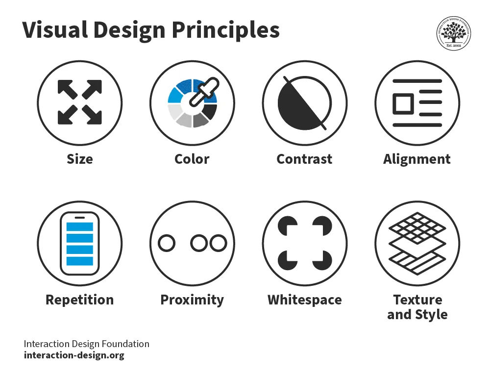
The 8 visual design principles.
In web design , visual hierarchy uses color and repetition to direct the user's attention. Color choice is crucial as it creates contrast between different elements. Repetition helps to organize the design—it uses recurring elements to establish consistency and familiarity.
In this video, Alan Dix, Professor and Expert in Human-Computer Interaction, explains how visual alignment affects how we read and absorb information:
Correspondence Techniques
Designers use correspondence techniques to align visual elements with their conceptual meanings. These techniques include color coding, spatial arrangement and specific imagery. In information visualization, different colors can represent various data sets. This correspondence aids users in quickly identifying trends and relationships .

Color coding enables the stakeholder to see the relationship and trend between the two pie charts easily.
In user interface design, correspondence techniques link elements with meaning. An example is color-coding notifications to state their nature. For instance, red for warnings and green for confirmation. These techniques are informative and intuitive and enhance the user experience.

The IxDF website uses blue for call-to-actions (CTAs) and red for warnings. These colors inform the user of the nature of the action of buttons and other interactive elements.
Perception and Interpretation
If visual language is how designers create representations, then visual perception and interpretation are how users receive those representations. Consider a painting—the viewer’s eyes take in colors, shapes and lines, and the brain perceives these visual elements as a painting.
In this video, Alan Dix explains how the interplay of sensation, perception and culture is crucial to understanding visual experiences in design:
Copyright holder: Michael Murphy _ Appearance time: 07:19 - 07:37 _ Link: https://www.youtube.com/watch?v=C67JuZnBBDc
Visual perception principles are essential for creating compelling, engaging visual representations. For example, Gestalt principles explain how we perceive visual information. These rules describe how we group similar items, spot patterns and simplify complex images. Designers apply Gestalt principles to arrange content on websites and other interfaces. This application creates visually appealing and easily understood designs.
In this video, design expert and teacher Mia Cinelli discusses the significance of Gestalt principles in visual design . She introduces fundamental principles, like figure/ground relationships, similarity and proximity.
Interpretation
Everyone's experiences, culture and physical abilities dictate how they interpret visual representations. For this reason, designers carefully consider how users interpret their visual representations. They employ user research and testing to ensure their designs are attractive and functional.

Leonardo da Vinci's "Mona Lisa", is one of the most famous paintings in the world. The piece is renowned for its subject's enigmatic expression. Some interpret her smile as content and serene, while others see it as sad or mischievous. Not everyone interprets this visual representation in the same way.
Color is an excellent example of how one person, compared to another, may interpret a visual element. Take the color red:
In Chinese culture, red symbolizes luck, while in some parts of Africa, it can mean death or illness.
A personal experience may mean a user has a negative or positive connotation with red.
People with protanopia and deuteranopia color blindness cannot distinguish between red and green.
In this video, Joann and Arielle Eckstut, leading color consultants and authors, explain how many factors influence how we perceive and interpret color:
Learn More about Visual Representation
Read Alan Blackwell’s chapter on visual representation from The Encyclopedia of Human-Computer Interaction.
Learn about the F-Shaped Pattern For Reading Web Content from Jakob Nielsen.
Read Smashing Magazine’s article, Visual Design Language: The Building Blocks Of Design .
Take the IxDF’s course, Perception and Memory in HCI and UX .
Questions related to Visual Representation
Some highly cited research on visual representation and related topics includes:
Roland, P. E., & Gulyás, B. (1994). Visual imagery and visual representation. Trends in Neurosciences, 17(7), 281-287. Roland and Gulyás' study explores how the brain creates visual imagination. They look at whether imagining things like objects and scenes uses the same parts of the brain as seeing them does. Their research shows the brain uses certain areas specifically for imagination. These areas are different from the areas used for seeing. This research is essential for understanding how our brain works with vision.
Lurie, N. H., & Mason, C. H. (2007). Visual Representation: Implications for Decision Making. Journal of Marketing, 71(1), 160-177.
This article looks at how visualization tools help in understanding complicated marketing data. It discusses how these tools affect decision-making in marketing. The article gives a detailed method to assess the impact of visuals on the study and combination of vast quantities of marketing data. It explores the benefits and possible biases visuals can bring to marketing choices. These factors make the article an essential resource for researchers and marketing experts. The article suggests using visual tools and detailed analysis together for the best results.
Lohse, G. L., Biolsi, K., Walker, N., & Rueter, H. H. (1994, December). A classification of visual representations. Communications of the ACM, 37(12), 36+.
This publication looks at how visuals help communicate and make information easier to understand. It divides these visuals into six types: graphs, tables, maps, diagrams, networks and icons. The article also looks at different ways these visuals share information effectively.
If you’d like to cite content from the IxDF website , click the ‘cite this article’ button near the top of your screen.
Some recommended books on visual representation and related topics include:
Chaplin, E. (1994). Sociology and Visual Representation (1st ed.) . Routledge.
Chaplin's book describes how visual art analysis has changed from ancient times to today. It shows how photography, post-modernism and feminism have changed how we see art. The book combines words and images in its analysis and looks into real-life social sciences studies.
Mitchell, W. J. T. (1994). Picture Theory. The University of Chicago Press.
Mitchell's book explores the important role and meaning of pictures in the late twentieth century. It discusses the change from focusing on language to focusing on images in cultural studies. The book deeply examines the interaction between images and text in different cultural forms like literature, art and media. This detailed study of how we see and read visual representations has become an essential reference for scholars and professionals.
Koffka, K. (1935). Principles of Gestalt Psychology. Harcourt, Brace & World.
"Principles of Gestalt Psychology" by Koffka, released in 1935, is a critical book in its field. It's known as a foundational work in Gestalt psychology, laying out the basic ideas of the theory and how they apply to how we see and think. Koffka's thorough study of Gestalt psychology's principles has profoundly influenced how we understand human perception. This book has been a significant reference in later research and writings.
A visual representation, like an infographic or chart, uses visual elements to show information or data. These types of visuals make complicated information easier to understand and more user-friendly.
Designers harness visual representations in design and communication. Infographics and charts, for instance, distill data for easier audience comprehension and retention.
For an introduction to designing basic information visualizations, take our course, Information Visualization .
Text is a crucial design and communication element, transforming language visually. Designers use font style, size, color and layout to convey emotions and messages effectively.
Designers utilize text for both literal communication and aesthetic enhancement. Their typography choices significantly impact design aesthetics, user experience and readability.
Designers should always consider text's visual impact in their designs. This consideration includes font choice, placement, color and interaction with other design elements.
In this video, design expert and teacher Mia Cinelli teaches how Gestalt principles apply to typography:
Designers use visual elements in projects to convey information, ideas, and messages. Designers use images, colors, shapes and typography for impactful designs.
In UI/UX design, visual representation is vital. Icons, buttons and colors provide contrast for intuitive, user-friendly website and app interfaces.
Graphic design leverages visual representation to create attention-grabbing marketing materials. Careful color, imagery and layout choices create an emotional connection.
Product design relies on visual representation for prototyping and idea presentation. Designers and stakeholders use visual representations to envision functional, aesthetically pleasing products.
Our brains process visuals 60,000 times faster than text. This fact highlights the crucial role of visual representation in design.
Our course, Visual Design: The Ultimate Guide , teaches you how to use visual design elements and principles in your work effectively.
Visual representation, crucial in UX, facilitates interaction, comprehension and emotion. It combines elements like images and typography for better interfaces.
Effective visuals guide users, highlight features and improve navigation. Icons and color schemes communicate functions and set interaction tones.
UX design research shows visual elements significantly impact emotions. 90% of brain-transmitted information is visual.
To create functional, accessible visuals, designers use color contrast and consistent iconography. These elements improve readability and inclusivity.
An excellent example of visual representation in UX is Apple's iOS interface. iOS combines a clean, minimalist design with intuitive navigation. As a result, the operating system is both visually appealing and user-friendly.
Michal Malewicz, Creative Director and CEO at Hype4, explains why visual skills are important in design:
Learn more about UI design from Michal in our Master Class, Beyond Interfaces: The UI Design Skills You Need to Know .
The fundamental principles of effective visual representation are:
Clarity : Designers convey messages clearly, avoiding clutter.
Simplicity : Embrace simple designs for ease and recall.
Emphasis : Designers highlight key elements distinctively.
Balance : Balance ensures design stability and structure.
Alignment : Designers enhance coherence through alignment.
Contrast : Use contrast for dynamic, distinct designs.
Repetition : Repeating elements unify and guide designs.
Designers practice these principles in their projects. They also analyze successful designs and seek feedback to improve their skills.
Read our topic description of Gestalt principles to learn more about creating effective visual designs. The Gestalt principles explain how humans group elements, recognize patterns and simplify object perception.
Color theory is vital in design, helping designers craft visually appealing and compelling works. Designers understand color interactions, psychological impacts and symbolism. These elements help designers enhance communication and guide attention.
Designers use complementary , analogous and triadic colors for contrast, harmony and balance. Understanding color temperature also plays a crucial role in design perception.
Color symbolism is crucial, as different colors can represent specific emotions and messages. For instance, blue can symbolize trust and calmness, while red can indicate energy and urgency.
Cultural variations significantly influence color perception and symbolism. Designers consider these differences to ensure their designs resonate with diverse audiences.
For actionable insights, designers should:
Experiment with color schemes for effective messaging.
Assess colors' psychological impact on the audience.
Use color contrast to highlight critical elements.
Ensure color choices are accessible to all.
In this video, Joann and Arielle Eckstut, leading color consultants and authors, give their six tips for choosing color:
Learn more about color from Joann and Arielle in our Master Class, How To Use Color Theory To Enhance Your Designs .
Typography and font choice are crucial in design, impacting readability and mood. Designers utilize them for effective communication and expression.
Designers' perception of information varies with font type. Serif fonts can imply formality, while sans-serifs can give a more modern look.
Typography choices by designers influence readability and user experience. Well-spaced, distinct fonts enhance readability, whereas decorative fonts may hinder it.
Designers use typography to evoke emotions and set a design's tone. Choices in font size, style and color affect the emotional impact and message clarity.
Designers use typography to direct attention, create hierarchy and establish rhythm. These benefits help with brand recognition and consistency across mediums.
Read our article to learn how web fonts are critical to the online user experience .
Designers create a balance between simplicity and complexity in their work. They focus on the main messages and highlight important parts. Designers use the principles of visual hierarchy, like size, color and spacing. They also use empty space to make their designs clear and understandable.
The Gestalt law of Prägnanz suggests people naturally simplify complex images. This principle aids in making even intricate information accessible and engaging.
Through iteration and feedback, designers refine visuals. They remove extraneous elements and highlight vital information. Testing with the target audience ensures the design resonates and is comprehensible.
Michal Malewicz explains how to master hierarchy in UI design using the Gestalt rule of proximity:
Answer a Short Quiz to Earn a Gift
Why do designers use visual representation?
- To guarantee only a specific audience can understand the information
- To replace the need for any form of written communication
- To simplify complex information and make it understandable
Which type of visual representation helps to compare data?
- Article images
- Line charts
- Text paragraphs
What is the main purpose of visual hierarchy in design?
- To decorate the design with more colors
- To guide the viewer’s attention to the most important elements first
- To provide complex text for high-level readers
How does color impact visual representation?
- It has no impact on the design at all.
- It helps to distinguish different elements and set the mood.
- It makes the design less engaging for a serious mood.
Why is consistency important in visual representation?
- It limits creativity, but allows variation in design.
- It makes sure the visual elements are cohesive and easy to understand.
- It makes the design unpredictable yet interesting.
Better luck next time!
Do you want to improve your UX / UI Design skills? Join us now
Congratulations! You did amazing
You earned your gift with a perfect score! Let us send it to you.
Check Your Inbox
We’ve emailed your gift to [email protected] .
Literature on Visual Representation
Here’s the entire UX literature on Visual Representation by the Interaction Design Foundation, collated in one place:
Learn more about Visual Representation
Take a deep dive into Visual Representation with our course Perception and Memory in HCI and UX .
How does all of this fit with interaction design and user experience? The simple answer is that most of our understanding of human experience comes from our own experiences and just being ourselves. That might extend to people like us, but it gives us no real grasp of the whole range of human experience and abilities. By considering more closely how humans perceive and interact with our world, we can gain real insights into what designs will work for a broader audience: those younger or older than us, more or less capable, more or less skilled and so on.
“You can design for all the people some of the time, and some of the people all the time, but you cannot design for all the people all the time.“ – William Hudson (with apologies to Abraham Lincoln)
While “design for all of the people all of the time” is an impossible goal, understanding how the human machine operates is essential to getting ever closer. And of course, building solutions for people with a wide range of abilities, including those with accessibility issues, involves knowing how and why some human faculties fail. As our course tutor, Professor Alan Dix, points out, this is not only a moral duty but, in most countries, also a legal obligation.
Portfolio Project
In the “ Build Your Portfolio: Perception and Memory Project ”, you’ll find a series of practical exercises that will give you first-hand experience in applying what we’ll cover. If you want to complete these optional exercises, you’ll create a series of case studies for your portfolio which you can show your future employer or freelance customers.
This in-depth, video-based course is created with the amazing Alan Dix , the co-author of the internationally best-selling textbook Human-Computer Interaction and a superstar in the field of Human-Computer Interaction . Alan is currently a professor and Director of the Computational Foundry at Swansea University.
Gain an Industry-Recognized UX Course Certificate
Use your industry-recognized Course Certificate on your resume , CV , LinkedIn profile or your website.
All open-source articles on Visual Representation
Data visualization for human perception.

The Key Elements & Principles of Visual Design

- 1.1k shares
Guidelines for Good Visual Information Representations

- 5 years ago
Philosophy of Interaction
Information visualization – an introduction to multivariate analysis.

- 8 years ago
Aesthetic Computing
How to represent linear data visually for information visualization.

Open Access—Link to us!
We believe in Open Access and the democratization of knowledge . Unfortunately, world-class educational materials such as this page are normally hidden behind paywalls or in expensive textbooks.
If you want this to change , cite this page , link to us, or join us to help us democratize design knowledge !
Privacy Settings
Our digital services use necessary tracking technologies, including third-party cookies, for security, functionality, and to uphold user rights. Optional cookies offer enhanced features, and analytics.
Experience the full potential of our site that remembers your preferences and supports secure sign-in.
Governs the storage of data necessary for maintaining website security, user authentication, and fraud prevention mechanisms.
Enhanced Functionality
Saves your settings and preferences, like your location, for a more personalized experience.
Referral Program
We use cookies to enable our referral program, giving you and your friends discounts.
Error Reporting
We share user ID with Bugsnag and NewRelic to help us track errors and fix issues.
Optimize your experience by allowing us to monitor site usage. You’ll enjoy a smoother, more personalized journey without compromising your privacy.
Analytics Storage
Collects anonymous data on how you navigate and interact, helping us make informed improvements.
Differentiates real visitors from automated bots, ensuring accurate usage data and improving your website experience.
Lets us tailor your digital ads to match your interests, making them more relevant and useful to you.
Advertising Storage
Stores information for better-targeted advertising, enhancing your online ad experience.
Personalization Storage
Permits storing data to personalize content and ads across Google services based on user behavior, enhancing overall user experience.
Advertising Personalization
Allows for content and ad personalization across Google services based on user behavior. This consent enhances user experiences.
Enables personalizing ads based on user data and interactions, allowing for more relevant advertising experiences across Google services.
Receive more relevant advertisements by sharing your interests and behavior with our trusted advertising partners.
Enables better ad targeting and measurement on Meta platforms, making ads you see more relevant.
Allows for improved ad effectiveness and measurement through Meta’s Conversions API, ensuring privacy-compliant data sharing.
LinkedIn Insights
Tracks conversions, retargeting, and web analytics for LinkedIn ad campaigns, enhancing ad relevance and performance.
LinkedIn CAPI
Enhances LinkedIn advertising through server-side event tracking, offering more accurate measurement and personalization.
Google Ads Tag
Tracks ad performance and user engagement, helping deliver ads that are most useful to you.
Share Knowledge, Get Respect!
or copy link
Cite according to academic standards
Simply copy and paste the text below into your bibliographic reference list, onto your blog, or anywhere else. You can also just hyperlink to this page.
New to UX Design? We’re Giving You a Free ebook!

Download our free ebook The Basics of User Experience Design to learn about core concepts of UX design.
In 9 chapters, we’ll cover: conducting user interviews, design thinking, interaction design, mobile UX design, usability, UX research, and many more!
MindManager
Guide to understanding process maps

What is a process map?
A process map is a visual representation of a task, process, or workflow. Process maps are a powerful planning and management tool that help you improve and streamline a process's workflow.
Process maps provide a visual guide for a process, helping you see all required steps in sequential order. This framework gives you a broad, big-picture overview of the process and a way to explore the more specific details in each step or stage.
Process map elements
Process maps have a few key elements that help represent and organize the various steps in your process. These symbols are based on Unified Modeling Language (UML), the same international standard used for flowcharts . Common process map features include:
| Flow | The flow is indicated by lines or arrows connecting the different steps and tasks. | |
| Process step | Rectangles represent process steps. Many elements of your process map will likely be simple process steps. | |
| Subprocess | These are also called subroutines and are represented by a rectangle or square with two vertical lines through it. This symbol is useful for showing a series of actions within a particular process step. | |
| Decisions | Diamonds are used to indicate decision points in your process map. Typically, diverging arrows follow a decision symbol, prompting you to choose which path to follow depending on which choice you made. | |
| Start and end points | In UML, start and end points are represented by a rounded rectangle or oval, also referred to as a "terminator symbol." |
Types of process maps
There are a few types of process maps, each with different types of projects that would be the best match. Review the various types of process maps, and choose the type that is the best fit for your needs.
SIPOC stands for Supplier, Input, Process, Output, Customer. This type of process map summarizes the flow of a process from beginning to end and is a valuable tool for gathering relevant information relating to a process and organizing it visually. SIPOC maps are commonly used in manufacturing and production.
Deployment map
A deployment map, also referred to as a cross-functional flowchart, is a visual tool for communicating the steps and stakeholders of a particular process. Deployment maps are especially helpful when a process includes many contributors across different departments or business functions. A deployment map could be used to visualize a shipping or fulfillment process where different business partners handle different steps.
Swimlane map
Similar to deployment maps, swimlane maps show the steps of a process and who is responsible for each step. Swimlane maps use rows or columns—resembling the lanes in a swimming pool—to represent each stakeholder. An HR team could use a swimlane map to create a detailed breakdown of responsibilities for a process like employee onboarding.
Value stream map
A value stream map takes the process map format to the next level by including the duration of each step and additional details about materials, inventory, and other relevant information. Also known as material and information flow charts (MIFC), value stream maps are typically used to show the steps of a production process, including how long each step takes and how much product is being handled at each stage.
When to use a process map
Process maps show events that lead to an end goal or outcome. While we explored some example use cases for process mapping in the section above, here are a few more ideas for when to use a process map in various industries.
Document marketing workflows
A marketing department could use a process map to document technical workflows like SEO audits or digital ad implementation. Having a visual resource to refer back to helps ensure everyone is on the same page and helps when onboarding and training new team members.
Visualize finance processes and tasks
A process map could be a useful way to visualize the processes in an accounts payable department where different team members are onboarding new vendors, processing orders, and making payments. Process maps help you stay organized and show details like which team members are responsible for which steps in the process.
Show the steps in a supply chain
Similar to the finance example, supply chain management also involves pipelines and workflows where different elements are at different steps at different times. Process maps, especially value stream maps, help logistics professionals document and organize complex supply chain information.
Guide sales strategies and relationships
Sales teams can use a process map to create a visual guide for their lead management activities. With a process map, a salesperson could plot their whole sales process and pipeline, from initial introductions with a prospect to closing the deal and maintaining that customer relationship.
Benefits of process mapping
Process maps allow you to document and organize the steps in a process. Benefits of process mapping include:
Saving time and increasing efficiency
You can streamline projects, problem-solving, and decision-making with a process map. This systematic approach to process management helps you simplify your projects, making them quicker and more efficient.
Improving collaboration
Process maps provide a shared space for documenting the steps of a project. With an organized, visual reference to return to throughout the project, everyone will be on the same page regarding expectations. Process mapping helps your team collaborate and communicate effectively from the project's launch to its conclusion.
Communicating ideas effectively
Process maps break down processes into simple, digestible steps, making even the most complex processes easier to understand and discuss. To boost comprehension, visualize your workflow with a process map.
Providing documentation
If you make a process map to document a process, it will be much easier to replicate it multiple times. To ensure your team members are all doing a specific task in a specific way, write the steps down in a process map. Not only does it make processes easier to replicate—but it also helps with onboarding and training new hires.
How to make a process map
Making a process map is straightforward. You start with a task or process you want to map. Then, you list the steps involved. With each step, you add details such as who is responsible for completing the task(s) required in that step.
As you're creating a process map, you might come across a step that has slowed the process down in the past—this is your opportunity to streamline the process and make it more efficient.
To make your own process map, follow these steps:
- Identify the process you want to map. Maybe it's a process you want to document to have a reference for training, or it could be a process you want to review to streamline it and make it more efficient.
- Identify the steps and activities involved. Before putting this information into the process map format, simply write everything in a list, making it easier to organize into a visual format later.
- Put the steps in order. Determine the sequence of events needed to complete the process successfully.
- Create your process map. Build your process map using your ordered list of steps and simple process map symbols. If you use the deployment map, swimlane map, or value stream map format, be sure to include information about which team member is responsible for which steps.
- Review, revise, and finalize. Discuss the process map with your team, making tweaks and edits as necessary. Once you're finished, you can continue referring to your process map throughout the project.
Why use MindManager to make process maps
With a process map software like MindManager , you can create powerful, digital process maps to help you organize and visualize your business processes. Features of MindManager include:
- User-friendly, intuitive interface
- Extensive image library—over 700 topic images, icons, and symbols to add to your process maps
- Convenient file storage, retrieval, and sharing
- Powerful integrations with file storage apps like Box and OneDrive
- Google Docs integration via Zapier
- Numerous templates, tools, and features to facilitate brainstorming and strategic planning
- Google Chrome extension—MindManager Snap—to easily collect and import text, links, and images from the web
- Ability to add rich data—links, images, and documents—directly to your diagrams and charts
MindManager boosts your productivity with premade templates and various user-friendly features and tools for creating dynamic visualizations. With MindManager, you can easily capture data, organize information, and communicate clearly about complex topics.
Process map templates
MindManager comes pre-installed with process map templates. To use these templates:
- Open MindManager
- Click NEW in the navigation menu
- Select the template you want to use
- A preview screen will appear - check to see if you'd like to use your selected template
- Select 'Create Map'
- Customize the template for your specific project

Process map FAQs
What does a process map show.
A process map shows the sequential steps involved in any process and information about who is responsible for each step. Some process maps include additional information about expected timelines or inventory details.
What symbols are used in a process map?
Common process map symbols are similar to those used for flowcharts. This includes symbols that represent : start and end points, process steps, subprocesses, and decision points.
What are the three main components of process mapping?
The three major components of process mapping are inputs, outputs, and process steps. Inputs include things that add information to the process map, such as research documents, orders, and emails. Outputs are things produced during or at the end of the process, such as receipts, presentations, and reports.
What are the differences between a process map and a flowchart?
Process maps and flowcharts are very similar—they even share some of the same symbols. The main difference is that some flowcharts, such as decision trees , visualize a decision process rather than a workflow.
Prioritize efficiency—make a process map
Process maps provide a framework for visualizing the steps required within a particular workflow. With a process map, you can record the various tasks that make up a process and information about who is responsible for each task.
Process mapping helps you streamline processes and save time—all while improving communication and creating valuable documentation you can refer to again and again.
Visualize more with MindManager
MindManager helps you communicate ideas in new and unique ways. With MindManager, your ideas come to life right before your eyes. To make your first process map, give MindManager a try today .
Related Articles

by MindManager Blog
What is business process mapping?
March 19, 2020

Process mapping tools you should adopt today
July 7, 2022

5 popular process design tools that improve workflow documentation
June 25, 2020

3 types of process design to help you map your business procedures
June 23, 2020
Other types of maps and charts
Task and project management, problem solving/ decision making, brainstorming, organizing data, process mapping, try the full version of mindmanager free for 30 days.

3 diagrams to make your processes more visual
Reading time: about 5 min
- Process improvement
Process visualization helps provide another perspective of how your workflows, processes, and systems work across your team. By objectively seeing the details behind your process, your team can troubleshoot and plan changes more effectively. You can keep stakeholders in the loop and make changes that are informed by your real circumstances.
To help you visualize processes, there are different types of visuals that are particularly helpful—in this blog post we talk about three. You can adapt these diagrams to fit your organization, use cases, and teams.
Flowchart with swimlanes
Swimlane flowcharts help to visualize the interactions and connections between various aspects of a process including hand-offs from one team or department to another. With the visuals depicted in a swimlane flowchart, your team can identify inefficiencies and redundancies, bringing clarity and focus to operations and process structures.
Sometimes referred to as cross-functional diagrams, these diagrams resemble a swimming pool with marked lanes that are used to designate different sections of a process.
When would you use a flowchart with swimlanes?
Using symbols and both vertical and horizontal lines, a flowchart with swimlanes helps teams see how processes are constrained, where there are potential bottlenecks, and where processes should be cleaned up or clarified.
- Visualize complex processes: Flowchart with swimlanes are great for showing processes with multiple parties, moving parts, and contributions. You can see at-a-glance connections among different aspects of your organization while also understanding flow, transitions, and chronology.
- Depict actors or characters: Activity within your process is driven by different actors within and outside your organization. With a swimlanes chart, you can show the impact of each actor and how they keep the process moving along.
- Link events together: You can break your process down into distinct events within your diagram, yet link them together so your team understands what happens as you move from one event to the next.

- Process flow : With a process flow diagram, you can show how responsibility and action are divided in a process.

Funnel charts
Funnels empower you to visualize data, working just like real funnels to demonstrate the transition of information through a process. A funnel can show movement from one step to another, or a narrowing down of information.
Drawn to look like a real funnel, a funnel chart shows a progression through steps. The widest part of the funnel moves to the narrowest part of the funnel, showing the starting point transitioning all the way over to the endpoint. The first stage is the largest section, followed by successively smaller stages. Not everything that starts at the beginning of the funnel reaches the end of the funnel.
When would you use a funnel chart?
Used for marketing, operations, HR, and other types and structures of information and content, funnels are easy to adapt and modify to different purposes. You can start with a template and adapt it with specific details, or you can create a funnel from scratch. Often sales or marketing contexts are where funnels really shine.
- Great for high-level visuals: Funnels are helpful places to start for high-level conversations before you begin a deeper dive into the data.
- Easy to use and understand: Funnels show clear progressions from one step to the next and are relatively adaptable.
- Adaptable to different functional areas: You can use a funnel with different departments and functions within your organization.
- Shows transitions and change: For use cases where you need to visualize a change or evolution from a starting point to the end, funnel charts are ideal. One popular use is in marketing to show the customer journey: how new prospects become more familiar with a brand, make a purchase decision, and become enthusiastic fans.
- Horizontal funnel : Horizontal funnels are great for showing transitions that are time-bound or impacted by change. For each stage from left to right, you can show which teams are involved and what happens during that part of the process.

Roles and responsibilities framework
Through a roles and responsibilities framework, you can depict how employees work and report to each other within your company or while completing a project. Team members can quickly determine who they should check in with or ask about a particular issue, simplifying the training and onboarding process. This is a helpful type of chart to create for your team and adapt whenever new people join your organization.
Working from a framework template or from scratch, you can create a roles and responsibilities framework that reflects your specific use case.
Your roles and responsibilities chart may show a hierarchy among your team members, clarifying who in the organization reports to whom and what responsibilities they hold. These charts look something like a tree or network and can include names, photos, titles, and an accompanying list of responsibilities that go with different roles.
When would you use a roles and responsibilities framework?
You can use this type of diagram for an organizational chart, help new employees understand the organizational structure of your company, and use this diagram within your human resources department to help identify gaps and challenges in your organizational structure.
- Roles and responsibilities framework example : By visualizing the relationships between different roles, you can see how the responsibilities for each position relate to each other in this diagram.

Want access to more than 1,000 ready-to-use templates? Sign up for Lucidchart.
About Lucidchart
Lucidchart, a cloud-based intelligent diagramming application, is a core component of Lucid Software's Visual Collaboration Suite. This intuitive, cloud-based solution empowers teams to collaborate in real-time to build flowcharts, mockups, UML diagrams, customer journey maps, and more. Lucidchart propels teams forward to build the future faster. Lucid is proud to serve top businesses around the world, including customers such as Google, GE, and NBC Universal, and 99% of the Fortune 500. Lucid partners with industry leaders, including Google, Atlassian, and Microsoft. Since its founding, Lucid has received numerous awards for its products, business, and workplace culture. For more information, visit lucidchart.com.
Bring your bright ideas to life.
or continue with
By registering, you agree to our Terms of Service and you acknowledge that you have read and understand our Privacy Policy .
- Business Essentials
- Leadership & Management
- Credential of Leadership, Impact, and Management in Business (CLIMB)
- Entrepreneurship & Innovation
- Digital Transformation
- Finance & Accounting
- Business in Society
- For Organizations
- Support Portal
- Media Coverage
- Founding Donors
- Leadership Team

- Harvard Business School →
- HBS Online →
- Business Insights →
Business Insights
Harvard Business School Online's Business Insights Blog provides the career insights you need to achieve your goals and gain confidence in your business skills.
- Career Development
- Communication
- Decision-Making
- Earning Your MBA
- Negotiation
- News & Events
- Productivity
- Staff Spotlight
- Student Profiles
- Work-Life Balance
- AI Essentials for Business
- Alternative Investments
- Business Analytics
- Business Strategy
- Business and Climate Change
- Creating Brand Value
- Design Thinking and Innovation
- Digital Marketing Strategy
- Disruptive Strategy
- Economics for Managers
- Entrepreneurship Essentials
- Financial Accounting
- Global Business
- Launching Tech Ventures
- Leadership Principles
- Leadership, Ethics, and Corporate Accountability
- Leading Change and Organizational Renewal
- Leading with Finance
- Management Essentials
- Negotiation Mastery
- Organizational Leadership
- Power and Influence for Positive Impact
- Strategy Execution
- Sustainable Business Strategy
- Sustainable Investing
- Winning with Digital Platforms
17 Data Visualization Techniques All Professionals Should Know

- 17 Sep 2019
There’s a growing demand for business analytics and data expertise in the workforce. But you don’t need to be a professional analyst to benefit from data-related skills.
Becoming skilled at common data visualization techniques can help you reap the rewards of data-driven decision-making , including increased confidence and potential cost savings. Learning how to effectively visualize data could be the first step toward using data analytics and data science to your advantage to add value to your organization.
Several data visualization techniques can help you become more effective in your role. Here are 17 essential data visualization techniques all professionals should know, as well as tips to help you effectively present your data.
Access your free e-book today.
What Is Data Visualization?
Data visualization is the process of creating graphical representations of information. This process helps the presenter communicate data in a way that’s easy for the viewer to interpret and draw conclusions.
There are many different techniques and tools you can leverage to visualize data, so you want to know which ones to use and when. Here are some of the most important data visualization techniques all professionals should know.
Data Visualization Techniques
The type of data visualization technique you leverage will vary based on the type of data you’re working with, in addition to the story you’re telling with your data .
Here are some important data visualization techniques to know:
- Gantt Chart
- Box and Whisker Plot
- Waterfall Chart
- Scatter Plot
- Pictogram Chart
- Highlight Table
- Bullet Graph
- Choropleth Map
- Network Diagram
- Correlation Matrices
1. Pie Chart

Pie charts are one of the most common and basic data visualization techniques, used across a wide range of applications. Pie charts are ideal for illustrating proportions, or part-to-whole comparisons.
Because pie charts are relatively simple and easy to read, they’re best suited for audiences who might be unfamiliar with the information or are only interested in the key takeaways. For viewers who require a more thorough explanation of the data, pie charts fall short in their ability to display complex information.
2. Bar Chart

The classic bar chart , or bar graph, is another common and easy-to-use method of data visualization. In this type of visualization, one axis of the chart shows the categories being compared, and the other, a measured value. The length of the bar indicates how each group measures according to the value.
One drawback is that labeling and clarity can become problematic when there are too many categories included. Like pie charts, they can also be too simple for more complex data sets.
3. Histogram

Unlike bar charts, histograms illustrate the distribution of data over a continuous interval or defined period. These visualizations are helpful in identifying where values are concentrated, as well as where there are gaps or unusual values.
Histograms are especially useful for showing the frequency of a particular occurrence. For instance, if you’d like to show how many clicks your website received each day over the last week, you can use a histogram. From this visualization, you can quickly determine which days your website saw the greatest and fewest number of clicks.
4. Gantt Chart

Gantt charts are particularly common in project management, as they’re useful in illustrating a project timeline or progression of tasks. In this type of chart, tasks to be performed are listed on the vertical axis and time intervals on the horizontal axis. Horizontal bars in the body of the chart represent the duration of each activity.
Utilizing Gantt charts to display timelines can be incredibly helpful, and enable team members to keep track of every aspect of a project. Even if you’re not a project management professional, familiarizing yourself with Gantt charts can help you stay organized.
5. Heat Map

A heat map is a type of visualization used to show differences in data through variations in color. These charts use color to communicate values in a way that makes it easy for the viewer to quickly identify trends. Having a clear legend is necessary in order for a user to successfully read and interpret a heatmap.
There are many possible applications of heat maps. For example, if you want to analyze which time of day a retail store makes the most sales, you can use a heat map that shows the day of the week on the vertical axis and time of day on the horizontal axis. Then, by shading in the matrix with colors that correspond to the number of sales at each time of day, you can identify trends in the data that allow you to determine the exact times your store experiences the most sales.
6. A Box and Whisker Plot

A box and whisker plot , or box plot, provides a visual summary of data through its quartiles. First, a box is drawn from the first quartile to the third of the data set. A line within the box represents the median. “Whiskers,” or lines, are then drawn extending from the box to the minimum (lower extreme) and maximum (upper extreme). Outliers are represented by individual points that are in-line with the whiskers.
This type of chart is helpful in quickly identifying whether or not the data is symmetrical or skewed, as well as providing a visual summary of the data set that can be easily interpreted.
7. Waterfall Chart

A waterfall chart is a visual representation that illustrates how a value changes as it’s influenced by different factors, such as time. The main goal of this chart is to show the viewer how a value has grown or declined over a defined period. For example, waterfall charts are popular for showing spending or earnings over time.
8. Area Chart

An area chart , or area graph, is a variation on a basic line graph in which the area underneath the line is shaded to represent the total value of each data point. When several data series must be compared on the same graph, stacked area charts are used.
This method of data visualization is useful for showing changes in one or more quantities over time, as well as showing how each quantity combines to make up the whole. Stacked area charts are effective in showing part-to-whole comparisons.
9. Scatter Plot

Another technique commonly used to display data is a scatter plot . A scatter plot displays data for two variables as represented by points plotted against the horizontal and vertical axis. This type of data visualization is useful in illustrating the relationships that exist between variables and can be used to identify trends or correlations in data.
Scatter plots are most effective for fairly large data sets, since it’s often easier to identify trends when there are more data points present. Additionally, the closer the data points are grouped together, the stronger the correlation or trend tends to be.
10. Pictogram Chart

Pictogram charts , or pictograph charts, are particularly useful for presenting simple data in a more visual and engaging way. These charts use icons to visualize data, with each icon representing a different value or category. For example, data about time might be represented by icons of clocks or watches. Each icon can correspond to either a single unit or a set number of units (for example, each icon represents 100 units).
In addition to making the data more engaging, pictogram charts are helpful in situations where language or cultural differences might be a barrier to the audience’s understanding of the data.
11. Timeline

Timelines are the most effective way to visualize a sequence of events in chronological order. They’re typically linear, with key events outlined along the axis. Timelines are used to communicate time-related information and display historical data.
Timelines allow you to highlight the most important events that occurred, or need to occur in the future, and make it easy for the viewer to identify any patterns appearing within the selected time period. While timelines are often relatively simple linear visualizations, they can be made more visually appealing by adding images, colors, fonts, and decorative shapes.
12. Highlight Table

A highlight table is a more engaging alternative to traditional tables. By highlighting cells in the table with color, you can make it easier for viewers to quickly spot trends and patterns in the data. These visualizations are useful for comparing categorical data.
Depending on the data visualization tool you’re using, you may be able to add conditional formatting rules to the table that automatically color cells that meet specified conditions. For instance, when using a highlight table to visualize a company’s sales data, you may color cells red if the sales data is below the goal, or green if sales were above the goal. Unlike a heat map, the colors in a highlight table are discrete and represent a single meaning or value.
13. Bullet Graph

A bullet graph is a variation of a bar graph that can act as an alternative to dashboard gauges to represent performance data. The main use for a bullet graph is to inform the viewer of how a business is performing in comparison to benchmarks that are in place for key business metrics.
In a bullet graph, the darker horizontal bar in the middle of the chart represents the actual value, while the vertical line represents a comparative value, or target. If the horizontal bar passes the vertical line, the target for that metric has been surpassed. Additionally, the segmented colored sections behind the horizontal bar represent range scores, such as “poor,” “fair,” or “good.”
14. Choropleth Maps

A choropleth map uses color, shading, and other patterns to visualize numerical values across geographic regions. These visualizations use a progression of color (or shading) on a spectrum to distinguish high values from low.
Choropleth maps allow viewers to see how a variable changes from one region to the next. A potential downside to this type of visualization is that the exact numerical values aren’t easily accessible because the colors represent a range of values. Some data visualization tools, however, allow you to add interactivity to your map so the exact values are accessible.
15. Word Cloud

A word cloud , or tag cloud, is a visual representation of text data in which the size of the word is proportional to its frequency. The more often a specific word appears in a dataset, the larger it appears in the visualization. In addition to size, words often appear bolder or follow a specific color scheme depending on their frequency.
Word clouds are often used on websites and blogs to identify significant keywords and compare differences in textual data between two sources. They are also useful when analyzing qualitative datasets, such as the specific words consumers used to describe a product.
16. Network Diagram

Network diagrams are a type of data visualization that represent relationships between qualitative data points. These visualizations are composed of nodes and links, also called edges. Nodes are singular data points that are connected to other nodes through edges, which show the relationship between multiple nodes.
There are many use cases for network diagrams, including depicting social networks, highlighting the relationships between employees at an organization, or visualizing product sales across geographic regions.
17. Correlation Matrix

A correlation matrix is a table that shows correlation coefficients between variables. Each cell represents the relationship between two variables, and a color scale is used to communicate whether the variables are correlated and to what extent.
Correlation matrices are useful to summarize and find patterns in large data sets. In business, a correlation matrix might be used to analyze how different data points about a specific product might be related, such as price, advertising spend, launch date, etc.
Other Data Visualization Options
While the examples listed above are some of the most commonly used techniques, there are many other ways you can visualize data to become a more effective communicator. Some other data visualization options include:
- Bubble clouds
- Circle views
- Dendrograms
- Dot distribution maps
- Open-high-low-close charts
- Polar areas
- Radial trees
- Ring Charts
- Sankey diagram
- Span charts
- Streamgraphs
- Wedge stack graphs
- Violin plots

Tips For Creating Effective Visualizations
Creating effective data visualizations requires more than just knowing how to choose the best technique for your needs. There are several considerations you should take into account to maximize your effectiveness when it comes to presenting data.
Related : What to Keep in Mind When Creating Data Visualizations in Excel
One of the most important steps is to evaluate your audience. For example, if you’re presenting financial data to a team that works in an unrelated department, you’ll want to choose a fairly simple illustration. On the other hand, if you’re presenting financial data to a team of finance experts, it’s likely you can safely include more complex information.
Another helpful tip is to avoid unnecessary distractions. Although visual elements like animation can be a great way to add interest, they can also distract from the key points the illustration is trying to convey and hinder the viewer’s ability to quickly understand the information.
Finally, be mindful of the colors you utilize, as well as your overall design. While it’s important that your graphs or charts are visually appealing, there are more practical reasons you might choose one color palette over another. For instance, using low contrast colors can make it difficult for your audience to discern differences between data points. Using colors that are too bold, however, can make the illustration overwhelming or distracting for the viewer.
Related : Bad Data Visualization: 5 Examples of Misleading Data
Visuals to Interpret and Share Information
No matter your role or title within an organization, data visualization is a skill that’s important for all professionals. Being able to effectively present complex data through easy-to-understand visual representations is invaluable when it comes to communicating information with members both inside and outside your business.
There’s no shortage in how data visualization can be applied in the real world. Data is playing an increasingly important role in the marketplace today, and data literacy is the first step in understanding how analytics can be used in business.
Are you interested in improving your analytical skills? Learn more about Business Analytics , our eight-week online course that can help you use data to generate insights and tackle business decisions.
This post was updated on January 20, 2022. It was originally published on September 17, 2019.

About the Author
.png)
Code Visualization: 4 Types of Diagrams and 5 Useful Tools

What Is Code Visualization?
Code visualization is the process of representing code in a graphical or pictorial format, rather than traditional lines of text. It entails creating visual representations of the structure, behavior, and evolution of software. Code visualization is about understanding the big picture of a codebase, seeing relationships and dependencies, and making sense of complex data structures.
Visualizing code can help bring clarity to complexity and make the abstract more tangible. When we visualize code, we are essentially translating the intricate language of computers into something more human and more comprehensible, both for developers and non-technical roles.
This is part of an extensive series of guides about [CI/CD] .
In this article:
Why is it important to visualize code.
- Using Diagrams for Code Visualization • Architecture Diagrams • Dependency Graphs • UML Diagrams • C4 Diagrams
- Key Features and Capabilities of Code Visualization Tools • Syntax Highlighting • Dependency Mapping • Interactive Debugging • Heatmaps • Collaborative Features • Integration with IDEs and Repositories
- 5 Notable Code Visualization Tools • CodeSee • Embold • Gource • SourceInsight • CppDepend
- Best Practices for Code Visualization • Use Annotations • Use Color Schemes Consistently • Provide Code Snippets • Real-Time Updates
Here are a few key benefits code visualization can provide for individual developers and development organizations:
- Identify and fix bugs more easily: Visual tools can highlight areas of the code where potential errors may lie. For instance, they can spotlight sections of the code that are unusually complex, which could signal potential bugs. Also, by visually tracing execution paths and data flows, it can be easier to find and fix bugs.
- Conceptualize large-scale projects: It's not uncommon to work on projects spanning thousands, if not millions, of lines of code. Code visualization can offer a bird's-eye view of the codebase, allowing developers to understand the overall structure and architecture of the software.
- Visualize dependencies: Code visualization can help visualize dependencies between modules or libraries. This can be particularly useful when making changes to the code or debugging, as it allows developers to anticipate the potential impact of their changes and take preventative measures.
- Onboard new software developers: Code visualization can help new developers understand the structure of the codebase, the relationships between different parts of the code, and where they need to focus their attention. This can significantly reduce the learning curve and allow new developers to become productive more quickly.
Using Diagrams for Code Visualization
One of the most effective ways to visualize code is through the use of diagrams. Diagrams provide a visual representation of the code's architecture, dependencies, and relationships, making it easier to grasp the overall structure of the system. Let's explore some commonly used diagrams for code visualization:
1. Architecture Diagrams
Architecture diagrams provide an overview of the system's structure and how its components interact with each other. They help us understand the high-level organization of the codebase and the flow of data and control between different modules.
These diagrams typically include components such as modules, classes, interfaces, and their relationships. By visualizing the architecture, we can identify areas of improvement, ensure proper separation of concerns, and make informed decisions about code organization.

2. Dependency Graphs
Dependency graphs are a powerful tool for visualizing the dependencies between different components of the codebase. They show how different modules or classes depend on each other, allowing us to identify potential issues such as circular dependencies or overly coupled code. By visualizing dependencies, we can make informed decisions about refactoring, identify areas of potential improvement, and ensure a modular and maintainable codebase.
3. UML Diagrams
Unified Modeling Language (UML) diagrams provide a standardized way of visualizing code. By using UML diagrams, we can communicate complex ideas and concepts in a standardized and easily understandable manner. Common types of UML diagrams include:
- Class diagrams: Show the relationship between classes, their attributes, and methods.
- Sequence diagrams: Illustrate the interaction between different objects over time. Activity diagrams: Help visualize the flow of control within a system.

4. C4 Diagrams
C4 diagrams are a relatively recent addition to the code visualization toolkit, designed to provide a multi-level, hierarchical representation of software architecture. These diagrams are broken down into four levels:
- Context Diagrams: Provide a bird's eye view of the system, showing how it interacts with users, external systems, and other software components.
- Container Diagrams: Visualize the high-level technology stack and how major parts of the system communicate with each other.
- Component Diagrams: This level illustrates the internal structure of individual containers, showing how various components within a container interact.
- Code Diagrams: Represents the actual code structure, including classes and interfaces, along with their relationships.

Source: Wikimedia
Learn more in our detailed guides to:
- C4 model Tools
Key Features and Capabilities of Code Visualization Tools
While it is possible to create code visualizations manually, many developers use dedicated code visualization tools, or visualization features of their integrated development environment (IDE). These tools provide useful features that can make code visualizations easier to create and more effective.
Syntax Highlighting
Syntax highlighting displays text, especially source code, in different colors and fonts according to the category of terms. This feature can make reading code easier and less error-prone, as it enables developers to quickly identify syntactic elements like keywords, variables, or function calls.
Syntax highlighting can also aid in spotting syntax errors. For instance, if a variable is not highlighted in the expected color, it may indicate that it has not been correctly declared or initialized. This feature, while seemingly simple, can be a major time-saver in coding and debugging.
Dependency Mapping
Understanding dependencies is essential for effective software development. Dependency mapping visually represents these relationships, helping developers understand how different parts of the code interact with each other.
With dependency mapping, developers can see at a glance which parts of the code depend on a particular module or function. This can inform decisions about code changes and help anticipate potential ripple effects. It can also aid in identifying areas of the code that may be overly complex or tightly coupled, signaling areas for potential refactoring.
Interactive Debugging
Interactive debugging features enable developers to step through the code execution one line at a time, watch the state of variables, and visually trace the execution path. This can provide invaluable insights into how the code behaves at runtime and help identify and fix bugs more efficiently.
Interactive debugging can also serve as a powerful learning tool. By visually stepping through the code, developers can gain a deeper understanding of how different programming constructs work, how data structures evolve over time, and how algorithms unfold.
Heatmaps are a visually intuitive method of displaying complex data. In the context of code visualization, heatmaps can be used to show various aspects of your codebase, such as the frequency of code changes, code complexity, or the number of bugs in different parts of the code. By using colors to represent these different metrics, heatmaps allow you to quickly identify hotspots in your codebase that may need attention.
Collaborative Features
Many code visualization tools provide collaborative capabilities, allowing multiple developers to work on the same codebase simultaneously, annotating and discussing the code in real time. This can greatly enhance team collaboration and communication, making it easier to identify and resolve potential issues early in the development process.
Integration with IDEs and Repositories
Finally, many code visualization tools integrate seamlessly with popular integrated development environments (IDEs) and code repositories. This integration allows you to visualize your code directly within your preferred coding environment, making it easier to understand and navigate your codebase. As mentioned, popular IDEs also include built-in code visualization tools.
5 Notable Code Visualization Tools
CodeSee is a dynamic code visualization tool that integrates seamlessly with development workflows and tools, including GitHub. It offers an array of features designed to provide deep insights into codebases, making it easier for developers and teams to understand, navigate, and manage their software projects effectively.

Key features include:
- Automatic codebase mapping: Automatically generates a map of the codebase, displaying connections between services, directories, and files.
- Visual review process: Maps changes in pull requests for better understanding and context of code changes.
- Interactive code tours: Features interactive, visual code tours to communicate ideas and code paths effectively.
- Feature planning and ownership maps: Provides tools for visualizing feature architecture and designating code ownership within a team.
- Side-by-side code comparison : Aids in comparing different versions of code and logically groups code for improved comprehension.
- Dependency identification: Helps in identifying and understanding dependencies in the codebase.
Learn more about the CodeSee platform

Embold is a developer tool that helps with code analysis, visualization, and refactoring. It helps developers understand their code's structure and quality, pinpoint potential problems, and refactor the code to enhance its maintainability and robustness.

Main features include:
- Code maps : You can create interactive displays of your source code, highlighting the relations and dependencies within your codebase.
- UML diagrams : Automatically create UML (Unified Modeling Language) diagrams, such as class and sequence diagrams.
- Graphs and charts : Create graphs that present various metrics like code complexity, test coverage, and code replication.
- Code heatmaps : Create heat maps that indicate sections of the code with the most usage or potential quality issues.
Gource is an open source tool that generates visualizations of codebases based on version control data.
- File tree visualization: Generates a tree-like visualization of the codebase, with each file represented as a node in the tree. The tree grows and changes to reflect the addition and modification of files.
- Customization: Allows users to customize the visualization in various ways, such as by specifying which types of files or events to include or exclude.
- Color coding: Uses different colors to represent different types of files or events, such as new files (green), modified files (yellow), and deleted files (red).
- Branching and merging: Shows the relationship between different branches and when they are merged together.
SourceInsight

Source Insight is a code editor and source code analysis tool developed by Source Dynamics. It is designed to help developers navigate, analyze, and understand large codebases.

- Syntax highlighting: Provides syntax highlighting for a variety of programming languages, which makes it easier to read and understand code.
- Code browsing: Allows developers to easily navigate through a codebase by displaying a list of variables, functions, and classes and their locations in the code.
- Cross-reference analysis: Allows developers to see how different parts of the codebase are interconnected and how they depend on each other.
- Interactive code maps: Creates interactive graphical maps of code relationships, which can be used to understand the structure and dependencies within a codebase.

CppDepend is a static code analysis tool specifically designed for C++ projects.

- Code metrics: These metrics are presented in an easy-to-understand visual format, allowing developers to quickly see the overall health of their codebase.
- Dependency analysis: Allows developers to visualize the dependencies between different parts of their codebase.
- Code map: Allows developers to visualize the structure of their codebase as a graph. This can be helpful for understanding the relationships between parts of the code.
- Code review: Allows developers to review code changes and provide feedback before they are committed to the codebase.
Best Practices for Code Visualization
Now that we've discussed the key features and capabilities of code visualization tools, let's review some best practices that can help you get the most out of code visualization.
Use Annotations
Annotations are a powerful way to add context to your code visualizations. By annotating your code, you can provide additional information that may not be immediately apparent from the code itself. This can be particularly useful when working with complex or unfamiliar codebases.
Use Color Schemes Consistently
Consistency is key when it comes to code visualization. By using consistent color schemes, you can make your visualizations more intuitive and easier to understand. For example, you might use different shades of red to represent different levels of code complexity, or different colors to represent different types of code elements.
Provide Code Snippets
Code snippets are another useful tool for code visualization. By providing small, self-contained pieces of code, you can make your visualizations more concrete and easier to understand. This can be particularly useful when explaining complex or abstract concepts.
Real-Time Updates
Finally, real-time updates can make your code visualizations more dynamic and engaging. By using automated tools that can update visualizations in real time, you can provide a live view of your codebase, making it easier to spot trends, identify issues, and track the progress of your development efforts.
In conclusion, code visualization is a vital tool for modern software development, providing clear, visual representations of complex codebases. By employing diagrams, dependency graphs, UML diagrams, and C4 diagrams, developers can gain a comprehensive understanding of their software's architecture, dependencies, and workflows.
Automated code visualization tools like CodeSee offer a range of features such as automated code diagrams, code maps and dependency mapping to enhance the visualization process. These capabilities not only simplify the process of identifying and resolving coding issues but also facilitate more effective collaboration and onboarding of new team members.
Learn more about the CodeSee platform and get started with code visualization.
See Additional Guides on Key CI/CD Topics
Together with our content partners, we have authored in-depth guides on several other topics that can also be useful as you explore the world of CI/CD .
Software Deployment
Authored by Codefresh
- Software Deployment in 2023: Checklist, Strategies & Tips
- What Is Blue/Green Deployment?
- What Are Canary Deployments? Process and Visual Example
- What Is Jenkins and How Does it Work? Intro and Tutorial
- Continuous Integration with Jenkins: A Practical Guide
- Jenkins X: How It Works and Creating Your First Project
Authored by Tigera
- What Is DevSecOps and What Do You Need to Succeed?
- 16 Amazing DevSecOps Tools to Shift Your Security Left

Lorem ipsum dolor sit amet, consectetur adipiscing elit. Suspendisse varius enim in eros elementum tristique. Duis cursus, mi quis viverra ornare, eros dolor interdum nulla, ut commodo diam libero vitae erat. Aenean faucibus nibh et justo cursus id rutrum lorem imperdiet. Nunc ut sem vitae risus tristique posuere. uis cursus, mi quis viverra ornare, eros dolor interdum nulla, ut commodo diam libero vitae erat. Aenean faucibus nibh et justo cursus id rutrum lorem imperdiet. Nunc ut sem vitae risus tristique posuere.
Start your code visibility journey with CodeSee today.
Initial Thoughts
Perspectives & resources, what is high-quality mathematics instruction and why is it important.
- Page 1: The Importance of High-Quality Mathematics Instruction
- Page 2: A Standards-Based Mathematics Curriculum
- Page 3: Evidence-Based Mathematics Practices
What evidence-based mathematics practices can teachers employ?
- Page 4: Explicit, Systematic Instruction
Page 5: Visual Representations
- Page 6: Schema Instruction
- Page 7: Metacognitive Strategies
- Page 8: Effective Classroom Practices
- Page 9: References & Additional Resources
- Page 10: Credits

Research Shows
- Students who use accurate visual representations are six times more likely to correctly solve mathematics problems than are students who do not use them. However, students who use inaccurate visual representations are less likely to correctly solve mathematics problems than those who do not use visual representations at all. (Boonen, van Wesel, Jolles, & van der Schoot, 2014)
- Students with a learning disability (LD) often do not create accurate visual representations or use them strategically to solve problems. Teaching students to systematically use a visual representation to solve word problems has led to substantial improvements in math achievement for students with learning disabilities. (van Garderen, Scheuermann, & Jackson, 2012; van Garderen, Scheuermann, & Poch, 2014)
- Students who use visual representations to solve word problems are more likely to solve the problems accurately. This was equally true for students who had LD, were low-achieving, or were average-achieving. (Krawec, 2014)
Visual representations are flexible; they can be used across grade levels and types of math problems. They can be used by teachers to teach mathematics facts and by students to learn mathematics content. Visual representations can take a number of forms. Click on the links below to view some of the visual representations most commonly used by teachers and students.
How does this practice align?
High-leverage practice (hlp).
- HLP15 : Provide scaffolded supports
CCSSM: Standards for Mathematical Practice
- MP1 : Make sense of problems and persevere in solving them.
Number Lines
Definition : A straight line that shows the order of and the relation between numbers.
Common Uses : addition, subtraction, counting

Strip Diagrams
Definition : A bar divided into rectangles that accurately represent quantities noted in the problem.
Common Uses : addition, fractions, proportions, ratios

Definition : Simple drawings of concrete or real items (e.g., marbles, trucks).
Common Uses : counting, addition, subtraction, multiplication, division

Graphs/Charts
Definition : Drawings that depict information using lines, shapes, and colors.
Common Uses : comparing numbers, statistics, ratios, algebra

Graphic Organizers
Definition : Visual that assists students in remembering and organizing information, as well as depicting the relationships between ideas (e.g., word webs, tables, Venn diagrams).
Common Uses : algebra, geometry
| Triangles | ||
|---|---|---|
| equilateral | – all sides are same length – all angles 60° | |
| isosceles | – two sides are same length – two angles are the same | |
| scalene | – no sides are the same length – no angles are the same | |
| right | – one angle is 90°(right angle) – opposite side of right angle is longest side (hypotenuse) | |
| obtuse | – one angle is greater than 90° | |
| acute | – all angles are less than 90° | |
Before they can solve problems, however, students must first know what type of visual representation to create and use for a given mathematics problem. Some students—specifically, high-achieving students, gifted students—do this automatically, whereas others need to be explicitly taught how. This is especially the case for students who struggle with mathematics and those with mathematics learning disabilities. Without explicit, systematic instruction on how to create and use visual representations, these students often create visual representations that are disorganized or contain incorrect or partial information. Consider the examples below.
Elementary Example
Mrs. Aldridge ask her first-grade students to add 2 + 4 by drawing dots.
Notice that Talia gets the correct answer. However, because Colby draws his dots in haphazard fashion, he fails to count all of them and consequently arrives at the wrong solution.
High School Example
Mr. Huang asks his students to solve the following word problem:
The flagpole needs to be replaced. The school would like to replace it with the same size pole. When Juan stands 11 feet from the base of the pole, the angle of elevation from Juan’s feet to the top of the pole is 70 degrees. How tall is the pole?
Compare the drawings below created by Brody and Zoe to represent this problem. Notice that Brody drew an accurate representation and applied the correct strategy. In contrast, Zoe drew a picture with partially correct information. The 11 is in the correct place, but the 70° is not. As a result of her inaccurate representation, Zoe is unable to move forward and solve the problem. However, given an accurate representation developed by someone else, Zoe is more likely to solve the problem correctly.

Manipulatives
Some students will not be able to grasp mathematics skills and concepts using only the types of visual representations noted in the table above. Very young children and students who struggle with mathematics often require different types of visual representations known as manipulatives. These concrete, hands-on materials and objects—for example, an abacus or coins—help students to represent the mathematical idea they are trying to learn or the problem they are attempting to solve. Manipulatives can help students develop a conceptual understanding of mathematical topics. (For the purpose of this module, the term concrete objects refers to manipulatives and the term visual representations refers to schematic diagrams.)
It is important that the teacher make explicit the connection between the concrete object and the abstract concept being taught. The goal is for the student to eventually understand the concepts and procedures without the use of manipulatives. For secondary students who struggle with mathematics, teachers should show the abstract along with the concrete or visual representation and explicitly make the connection between them.
A move from concrete objects or visual representations to using abstract equations can be difficult for some students. One strategy teachers can use to help students systematically transition among concrete objects, visual representations, and abstract equations is the Concrete-Representational-Abstract (CRA) framework.
If you would like to learn more about this framework, click here.
Concrete-Representational-Abstract Framework

- Concrete —Students interact and manipulate three-dimensional objects, for example algebra tiles or other algebra manipulatives with representations of variables and units.
- Representational — Students use two-dimensional drawings to represent problems. These pictures may be presented to them by the teacher, or through the curriculum used in the class, or students may draw their own representation of the problem.
- Abstract — Students solve problems with numbers, symbols, and words without any concrete or representational assistance.
CRA is effective across all age levels and can assist students in learning concepts, procedures, and applications. When implementing each component, teachers should use explicit, systematic instruction and continually monitor student work to assess their understanding, asking them questions about their thinking and providing clarification as needed. Concrete and representational activities must reflect the actual process of solving the problem so that students are able to generalize the process to solve an abstract equation. The illustration below highlights each of these components.

For Your Information
One promising practice for moving secondary students with mathematics difficulties or disabilities from the use of manipulatives and visual representations to the abstract equation quickly is the CRA-I strategy . In this modified version of CRA, the teacher simultaneously presents the content using concrete objects, visual representations of the concrete objects, and the abstract equation. Studies have shown that this framework is effective for teaching algebra to this population of students (Strickland & Maccini, 2012; Strickland & Maccini, 2013; Strickland, 2017).
Kim Paulsen discusses the benefits of manipulatives and a number of things to keep in mind when using them (time: 2:35).
Kim Paulsen, EdD Associate Professor, Special Education Vanderbilt University
View Transcript

Transcript: Kim Paulsen, EdD
Manipulatives are a great way of helping kids understand conceptually. The use of manipulatives really helps students see that conceptually, and it clicks a little more with them. Some of the things, though, that we need to remember when we’re using manipulatives is that it is important to give students a little bit of free time when you’re using a new manipulative so that they can just explore with them. We need to have specific rules for how to use manipulatives, that they aren’t toys, that they really are learning materials, and how students pick them up, how they put them away, the right time to use them, and making sure that they’re not distracters while we’re actually doing the presentation part of the lesson. One of the important things is that we don’t want students to memorize the algorithm or the procedures while they’re using the manipulatives. It really is just to help them understand conceptually. That doesn’t mean that kids are automatically going to understand conceptually or be able to make that bridge between using the concrete manipulatives into them being able to solve the problems. For some kids, it is difficult to use the manipulatives. That’s not how they learn, and so we don’t want to force kids to have to use manipulatives if it’s not something that is helpful for them. So we have to remember that manipulatives are one way to think about teaching math.
I think part of the reason that some teachers don’t use them is because it takes a lot of time, it takes a lot of organization, and they also feel that students get too reliant on using manipulatives. One way to think about using manipulatives is that you do it a couple of lessons when you’re teaching a new concept, and then take those away so that students are able to do just the computation part of it. It is true we can’t walk around life with manipulatives in our hands. And I think one of the other reasons that a lot of schools or teachers don’t use manipulatives is because they’re very expensive. And so it’s very helpful if all of the teachers in the school can pool resources and have a manipulative room where teachers can go check out manipulatives so that it’s not so expensive. Teachers have to know how to use them, and that takes a lot of practice.

- Visual Representation of Process

In most organisations, you will find that while they have a process, nobody seems to know it exactly, or even where to go to find it. The problem, it seems is with the way in which processes are documented. Process documents are usually lamented over at the time of their writing, then shelved without much thought at all. The reason for this I believe is that there is primarily only two times when a process document is actually referenced:
- When a new employee joins the team, and is shown how things are done
- When a higher manager asks “how does your team operate”
In my mind, I would much prefer a simpler process flow that is actually used by staff, even if it doesn’t cover every possible eventuality along the way. The visual process document provides the most effective way of presenting the flow of how we go about completing our tasks. Its typically printable on one page (though it might have to be A3), it’s pinnable to your office cubicle, and sometimes as importantly, can be pasted into powerpoint presentations for the business.
So how do you present your testing process?

About the Author
Joel Deutscher is an experienced performance test consultant, passionate about continuous improvement. Joel works with Planit's Technical Testing Services as a Principal Consultant in Sydney, Australia. You can read more about Joel on LinkedIn .
Comments are closed.
- Subscribe to RSS Follow on Twitter
Joel Deutscher is an experienced performance test consultant, passionate about continuous improvement. Joel works with Planit's Technical Testing Services as a Principal Consultant in Sydney, Australia.
- Decrease Indent in LoadRunner
- Bandwidth Emulation for Mac
- Stress testing by end users
- An Alternative to System Info Wallpaper
Copyright © 2011 Headwired . Powered by WordPress

Loading metrics
Open Access
Peer-reviewed
Research Article
Decoding dynamic visual scenes across the brain hierarchy
Roles Data curation, Formal analysis, Investigation, Methodology, Resources, Software, Validation, Visualization, Writing – original draft, Writing – review & editing
Affiliations School of Computer Science, Peking University, Beijing, China, Institute for Artificial Intelligence, Peking University, Beijing, China
Roles Formal analysis, Investigation, Validation, Visualization, Writing – original draft, Writing – review & editing
Affiliation School of Computing, University of Leeds, Leeds, United Kingdom
Roles Investigation, Writing – original draft, Writing – review & editing
Affiliation School of Computer Science, Centre for Human Brain Health, University of Birmingham, Birmingham, United Kingdom
Roles Investigation, Methodology, Validation, Visualization, Writing – original draft, Writing – review & editing
Roles Investigation, Validation, Writing – original draft, Writing – review & editing
Affiliation Institutes of Brain Science, State Key Laboratory of Medical Neurobiology, MOE Frontiers Center for Brain Science and Institute for Medical and Engineering Innovation, Eye & ENT Hospital, Fudan University, Shanghai, China
Roles Conceptualization, Funding acquisition, Investigation, Methodology, Project administration, Supervision, Writing – original draft, Writing – review & editing
* E-mail: [email protected] (ZY); [email protected] (JKL)
Roles Conceptualization, Funding acquisition, Investigation, Methodology, Project administration, Supervision, Validation, Visualization, Writing – original draft, Writing – review & editing
Affiliations School of Computing, University of Leeds, Leeds, United Kingdom, School of Computer Science, Centre for Human Brain Health, University of Birmingham, Birmingham, United Kingdom
- Ye Chen,
- Peter Beech,
- Ziwei Yin,
- Shanshan Jia,
- Jiayi Zhang,
- Zhaofei Yu,
- Jian K. Liu
- Published: August 2, 2024
- https://doi.org/10.1371/journal.pcbi.1012297
- Reader Comments
This is an uncorrected proof.
Understanding the computational mechanisms that underlie the encoding and decoding of environmental stimuli is a crucial investigation in neuroscience. Central to this pursuit is the exploration of how the brain represents visual information across its hierarchical architecture. A prominent challenge resides in discerning the neural underpinnings of the processing of dynamic natural visual scenes. Although considerable research efforts have been made to characterize individual components of the visual pathway, a systematic understanding of the distinctive neural coding associated with visual stimuli, as they traverse this hierarchical landscape, remains elusive. In this study, we leverage the comprehensive Allen Visual Coding—Neuropixels dataset and utilize the capabilities of deep learning neural network models to study neural coding in response to dynamic natural visual scenes across an expansive array of brain regions. Our study reveals that our decoding model adeptly deciphers visual scenes from neural spiking patterns exhibited within each distinct brain area. A compelling observation arises from the comparative analysis of decoding performances, which manifests as a notable encoding proficiency within the visual cortex and subcortical nuclei, in contrast to a relatively reduced encoding activity within hippocampal neurons. Strikingly, our results unveil a robust correlation between our decoding metrics and well-established anatomical and functional hierarchy indexes. These findings corroborate existing knowledge in visual coding related to artificial visual stimuli and illuminate the functional role of these deeper brain regions using dynamic stimuli. Consequently, our results suggest a novel perspective on the utility of decoding neural network models as a metric for quantifying the encoding quality of dynamic natural visual scenes represented by neural responses, thereby advancing our comprehension of visual coding within the complex hierarchy of the brain.
Author summary
Understanding how the brain processes visual information is a crucial area of neuroscience research. One of the main challenges is studying how the brain handles dynamic natural visual scenes. Although there has been progress in studying parts of the visual pathway, we still do not fully understand how different areas of the brain work together to process these scenes. Here we used the comprehensive Allen Visual Coding—Neuropixels dataset and advanced deep learning models to explore how the brain encodes and decodes visual information. We found that our model could accurately interpret visual scenes based on neural activity from various regions of the brain. Our findings show a strong link between our decoding results and established brain hierarchy indexes. This not only supports existing knowledge about visual coding but sheds light on the role of deeper brain regions in processing visual scenes. Our study suggests that decoding neural network models can be a valuable tool for understanding how the brain encodes visual information, providing new insights into the complex workings of the visual system in the brain.
Citation: Chen Y, Beech P, Yin Z, Jia S, Zhang J, Yu Z, et al. (2024) Decoding dynamic visual scenes across the brain hierarchy. PLoS Comput Biol 20(8): e1012297. https://doi.org/10.1371/journal.pcbi.1012297
Editor: Daniele Marinazzo, Ghent University, BELGIUM
Received: December 12, 2023; Accepted: July 3, 2024; Published: August 2, 2024
Copyright: © 2024 Chen et al. This is an open access article distributed under the terms of the Creative Commons Attribution License , which permits unrestricted use, distribution, and reproduction in any medium, provided the original author and source are credited.
Data Availability: The data used in this work are publicly available recordings from the Visual Coding - Neuropixels dataset, provided by the Allen Institute for Brain Science. The stimuli images and neural data are available at https://portal.brain-map.org/circuits-behavior/visual-coding-neuropixels . The code used to generate the results in this paper is available at https://github.com/beizai/Decoding .
Funding: This work was supported by the National Natural Science Foundation of China 62176003 and 62088102 and Beijing Nova Program 20230484362 (ZY) and the MOST of China 2022ZD0208604 and 2022ZD0208605 and National Natural Science Foundation of China Grants T2325008 and 820712002 (JZ), and Royal Society Newton Advanced Fellowship of UK Grant NAF-R1-191082 (JKL). The funders had no role in study design, data collection and analysis, decision to publish, or preparation of the manuscript.
Competing interests: The authors have declared that no competing interests exist.
Introduction
Over the course of several decades, extensive research has yielded deep insights into the neural encoding of various attributes within artificial visual stimuli, including features such as the direction of moving gratings. This wealth of knowledge has shed light on the encoding mechanisms employed by visual neurons located in different regions of the brain, particularly within the early visual processing systems, which include the retina [ 1 – 5 ], the lateral geniculate nuclei (LGN) [ 6 – 10 ], and the primary visual cortex (V1) [ 11 – 14 ]. Nonetheless, a formidable challenge remains in elucidating how neurons distributed across various regions of the brain represent natural scenes, comprising natural images and videos [ 15 – 18 ]. This challenge is particularly pronounced when investigating the neural coding of dynamic natural scenes, such as videos [ 19 – 24 ]. The visual system stands as a typical neural pathway that is of critical importance in mediating interactions with the external environment. A considerable expanse of the cerebral cortex is allocated to the processing of visual information [ 25 – 27 ]. This complex cascade of information processing unfolds as we receive copious sensory inputs from the external world and engage in higher-order cognitive functions following the orchestration of these inputs across various brain areas.
The retina serves as the inaugural site of the conversion of visual scenes into electrical signals, marking the initial phase in the trajectory of visual coding. These visual signals traverse the brain in the form of neural spikes, commencing their journey with the retinal ganglion cells, progressing through the LGN located in the thalamus, and ultimately arriving at the visual cortex. Within the realm of the visual cortex, two discernible information pathways, namely the dorsal and ventral streams, have been suggested to come into play [ 28 , 29 ]. In both streams, the initial point is V1, which serves as the pivotal site of early neural processing [ 30 ]. In the dorsal stream, where intricate spatial and locational information processing occurs, neural signals undergo further transmission to the anterior pretectal nuclei (APN) [ 31 , 32 ]. Simultaneously, within the ventral stream, which contributes to memory formation, the information travels a divergent route, eventually reaching the hippocampus [ 33 ]. The elucidation of how visual signals are encoded and subsequently decoded within the cerebral confines is a paramount inquiry in vision research [ 34 ]. In particular, the revelation of how visual scenes traverse a hierarchical neural structure within the brain constitutes a foundational inquiry that holds profound implications not only for the realm of vision but also for the broader computational principles governing the functioning of neurons and neuronal circuits [ 4 , 19 , 35 ].
Over the past several decades, the mechanism governing the encoding of visual scenes has undergone extensive investigation, culminating in a wealth of insightful perspectives on the encoding of specific visual attributes, including, but not limited to luminance contrast, directional motion, and velocity [ 4 , 13 , 35 ]. Moreover, these inquiries have been extended to encompass more intricate and holistic visual scenes, such as natural images and videos [ 16 , 19 , 36 ]. In contrast to encoding, the challenge of decoding visual information from neural signals has been predominantly approached from an engineering perspective. In this context, a variety of methodologies and models have been developed, primarily oriented at addressing classification tasks related to object categorization [ 37 – 39 ], as well as the endeavor of reconstructing pixel-level images [ 40 – 50 ]. These recent studies in decoding and the reconstruction of pixel-level imagery provide fresh perspectives that hold significant implications for the evaluation of visual neuroprosthetic devices and the advancement of vision restoration [ 51 – 54 ].
However, the interaction of encoding and decoding methodologies within the context of visual coding, especially those pertaining to dynamic natural scenes, remains an area marked by limited exploration. In this study, we undertake the endeavor of uniting these facets to offer a comprehensive perspective on visual coding. To accomplish this, we investigate a well-established and robust resource, the Allen Visual Coding—Neuropixels experimental dataset [ 55 ], utilizing a deep learning neural network decoding model [ 49 ]. Our exploration delves deep into the Allen Visual Coding—Neuropixels dataset, exploring it systematically to unravel the intricacies of visual coding distributed across a wide spectrum of hierarchical brain regions. These encompass three distinct regions within the nucleus, six segments within the visual cortex, and four divisions within the hippocampus. Using the power of our decoding model, we embark on the task of reconstructing every individual pixel within the images of the corresponding neural spikes. In this pursuit, we ascertain our capability to accurately decode video pixels from the neural activity of neurons located within the nucleus and the visual cortex, while discerning a significant decrease in decoding accuracy within the hippocampus. In particular, our findings reveal a strong correlation between our decoding accuracy and the classical encoding metrics obtained from experiments employing artificial stimuli. Furthermore, these findings extend to encompass the alignment of our decoding accuracy with the established anatomical and functional hierarchy indexes identified through experimental investigation. These significant outcomes underscore the substantive meaning and competence of our decoding model in deciphering visual information embedded within neural signals. Consequently, our study introduces an innovative approach to quantifying the extent to which visual information derived from dynamic scenes is encapsulated within neural signals from distinct cerebral regions.
Encoding and decoding dynamic visual scenes in different brain areas
To elucidate the hierarchical organization of visual processing within the intricate pathways of the brain, we used a robust and expansive experimental dataset, the Allen Visual Coding—Neuropixels dataset [ 55 ]. This dataset provides recordings from thousands of neurons within mice, captured simultaneously via neuropixels, across a diverse array of brain regions ( Fig 1 ). Our investigation focused on three principal brain regions, encompassing a total of 13 identified brain areas. These regions are delineated as the visual cortex (comprising VISp, VISl, VISrl, VISal, VISpm, and VISam) located at the uppermost tier of the brain, the hippocampus (encompassing CA1, CA3, DG, and SUB) located at an intermediary level, and the nucleus (encompassing LGN, lateral posterior nucleus—LP, and APN) located in the deeper recesses of the brain ( Fig 1A ).
- PPT PowerPoint slide
- PNG larger image
- TIFF original image
(A) A hierarchical structure of 13 brain areas in three brain regions of the visual cortex, hippocampus, and nucleus, was recorded in response to dynamic videos. The visual information flow is indicated by arrows. (B) The distribution of cell locations recorded in response to videos on multiple neuropixels. Each datapoint is an individual cell. (C) Example neuronal spike trains of 10 cells in each brain area in response to a video presentation. (D) The distribution of cell numbers in each brain area. (E) The firing activity showing means and standard deviations (SDs) of the spike counts averaged over the entire duration of video stimuli in each brain area. (F) The decoding workflow. A deep learning neural network decode takes the input of neural spikes and outputs images. The decoder performance indicates how much visual information is encoded by different brain areas. Visual scenes are natural movies presented as visual stimuli in the Allen Visual Coding—Neuropixels dataset ( https://portal.brain-map.org/circuits-behavior/visual-coding-neuropixels ).
https://doi.org/10.1371/journal.pcbi.1012297.g001
Within the Allen Visual Coding—Neuropixels dataset, a diverse pool of visual stimuli was deployed, ranging from well-designed artificial scenes, such as drifting gratings designed to assess fundamental tuning properties, to dynamic video scenes that have not been extensively investigated. Neurons were systematically recorded in response to these stimuli, with multiple neuropixels capturing a large set of cells distributed across a wide spectrum of brain areas ( Fig 1B ). Notably, the spiking activity observed in response to the video presentations exhibited dynamic temporal patterns both within individual cells and across the cell population ( Fig 1C ).
While previous studies have successfully characterized the encoding properties of artificial visual scenes, including the tuning of direction and orientation, across various brain regions [ 55 ], the encoding of dynamic video scenes remains comparatively less understood. Here we selected a subset of cells exhibiting firing activities in response to video stimuli. The cell count within this subset exhibited variation, ranging from 355 cells in CA3 to 2443 cells in CA1, with most brain regions comprising more than 800 cells ( Fig 1D , S1 Table ). The firing rates, including means and standard deviations ( Fig 1E ), as well as Fano factors and inter-spike intervals ( S1 Fig ), show a diverse range of values, yet demonstrate consistency across the distinct brain areas. This comprehensive dataset with high-quality neuronal recordings and dynamic video stimuli empowers our exploration into the representation of dynamic natural scenes across different brain regions.
The core focus of our study is the direct decoding of dynamic visual scenes from neural spikes. To achieve this, we leverage our previously developed deep learning model, which has been validated to decode image pixel data from neuronal spikes originating in the retina [ 49 ]. Here, we extend the application of this model to explore the intricacies of this expansive dataset. Our model, designed as an end-to-end deep learning neural network ( Methods ), receives sequences of spikes from a population of cells as input and generates, as output, the corresponding pixels of video frames associated with these spikes. By quantifying the fidelity and quality of the reconstructed images, we are equipped to study the extent to how visual information is encoded within distinct brain areas. It is a reasonable expectation that the nucleus and the visual cortex should exhibit a substantial information load, whereas the hippocampus is expected to bear relatively less visual information ( Fig 1F ).
Decoding model as a metric of visual scene encoding
Utilizing a consistent deep neural network framework, we focus on the task of decoding the same visual images by inputting distinct neural spike data originating from various brain regions. Our model exhibited a superb capability for decoding and reconstructing image pixels with a high degree of precision ( Fig 2A ). To evaluate the quality of the decoded images, we employed two widely accepted quantitative metrics: Structural Similarity (SSIM) and Peak Signal-to-Noise Ratio (PSNR). Both of these metrics were adeptly used as measures for assessing the performance of our decoding model, consistently yielding evaluations of the reconstructed image quality ( Fig 2B ), which are also robust to the variation of the model parameter settings ( S2 Fig ).
(A) Example of decoded video frame images using spikes of each individual brain area. The original images are on the top (Origin). The decoded images from each brain area are colored according to the visual cortex, nucleus, and hippocampus. (B) Decoding metrics, SSIM and PSNR, indicate the quality of decoded images in different brain areas. The random cases serve as decoding baselines (dash lines), using two shuffling scenarios, shuffled spikes in the primary visual cortex (VISp-shuffled), and all six areas of the visual cortex (VI-shuffled). The values in violin plots are computed with 400 test images in this and the following figures. Images are natural movies presented as visual stimuli in the Allen Visual Coding—Neuropixels dataset ( https://portal.brain-map.org/circuits-behavior/visual-coding-neuropixels ).
https://doi.org/10.1371/journal.pcbi.1012297.g002
A pronounced trend of visual coding decay was revealed as we traversed the hierarchical landscape of the visual information pathway. The primary visual cortex (VISp) emerged as the most proficient in rendering images with a high degree of fidelity, faithfully capturing the details of the stimuli. Furthermore, within the sub-regions, each of the six distinct brain areas located within the visual cortex, as well as the LGN and LP within the thalamus, and the APN within the midbrain, exhibited decoding results of considerable quality. These regions could effectively reconstruct a significant portion of the original image details. In contrast, results obtained from the hippocampus areas were notably inferior, reflected in diminished values of decoding metrics and a substantial loss of fine-grained details from the original stimuli.
To determine the significance of the decoding metrics obtained, we performed an experiment involving the random shuffling of spikes within the primary visual cortex (VISP-shuffled) and across all six regions of the visual cortex (VI-shuffled). This process effectively perturbed the temporal relationships between the spikes and the stimulus images, rendering the reconstruction process entirely random without any meaningful information. The decoding metrics SSIM and PSNR were measured for the data resulting from the shuffled spikes, serving as a baseline for comparison. Our decoding results consistently outperformed the shuffled baseline, underscoring the meaningful nature of our decoding approach and its capacity to faithfully reflect the extent of visual information encoded within neural spikes ( Fig 2B ).
Hippocampus encodes less visual information
To undertake a comprehensive quantification of how visual scenes are encoded across various brain areas, we aggregated all nearby sub-areas into three cohesive and interconnected macroscopic brain regions: the visual cortex, nucleus, and hippocampus. Using the collective neuronal spikes originating from these three distinct brain regions, we conducted a thorough examination of decoding outcomes and subsequently compared their performance across these regions ( Fig 3 ). In particular, the example decoded images in each region show a striking level of precision in image reconstruction, distinguishing them significantly from the results of shuffled spikes ( Fig 3A ). These favorable results were further validated by the decoding metrics SSIM and PSNR, which underscored the superior performance of both the visual cortex and the nucleus in contrast to the hippocampus ( Fig 3B ).
(A) Samples of original images (Origin) and decoded images in each combined brain region (Visual cortex, nucleus, hippocampus). The decoded results in shuffled spikes across all brain regions listed as a baseline. (B) Corresponding decoding metrics in each case of (A). SSIM and PSNR metrics in each brain region and baseline with shuffled data. (C) Decoding matrices where the diagonal elements are the values in (B) and the off-diagonal elements are the values of model generalizability, e.g., using the models trained on each brain area to predict other test brain areas. Marked values are the means of over 400 test images in this the following figures. Images are natural movies presented as visual stimuli in the Allen Visual Coding—Neuropixels dataset ( https://portal.brain-map.org/circuits-behavior/visual-coding-neuropixels ).
https://doi.org/10.1371/journal.pcbi.1012297.g003
To explore the generalizability of our decoding models, we applied a model trained on one specific brain region to data originating from different regions. This approach facilitated the construction of a decoding matrix ( Fig 3C ), wherein the diagonal elements reflect the model’s performance when trained and tested with data from the same brain region. In contrast, the off-diagonal elements represent the model’s generalizability, where the performance was trained with one region’s data and tested on another. Notably, we observed that the decoding models exhibited a remarkable degree of specificity, with relatively low generalizability. The decoding metrics associated with off-diagonal elements closely match the performance observed in the shuffled baseline, underscoring the distinctive nature of our decoding models ( Fig 3C ).
Robust decoding with a small set of cells
In pursuit of a more detailed comparison between different brain areas, we systematically replicated our decoding procedure, by employing controlled cell numbers from each region. To ensure a limited sampling representation, we randomly selected 800 cells from all six areas within the visual cortex, as well as the LGN, LP and CA1. This selection was made with the understanding that other regions possessed fewer than 800 cells. Remarkably, the decoding results derived from this subset of 800 cells closely match those obtained with the full number of cells ( Fig 4A ). This observation was further substantiated by the decoding metrics SSIM and PSNR. Furthermore, we explored two distinct scenarios wherein we mixed areas from the visual cortex, with or without VISp. In each case, decoding with 800 cells consistently yielded similar results. However, the decoding performance with CA1 remained notably inferior when contrasted with that of the visual cortex, LGN, and LP. The decoding models trained on individual brain areas exhibited remarkable specificity, demonstrating inferior performance when transferred to test data from other brain regions (evident in the off-diagonal metrics, which closely mirrored the shuffled baseline, as illustrated in Fig 4B ).
(A) Examples of decoded images with 800 cells of each brain area and two combined areas (VI-all: all combined six areas in the visual cortex; VI w/o VISp: combined five areas of the visual cortex without VISp). (B) Decoding metrics of SSIM and PSNR. Matrices show the decoding values using models trained on each brain area while testing on the same (diagonal) and different (off-diagonal) areas. Images are natural movies presented as visual stimuli in the Allen Visual Coding—Neuropixels dataset ( https://portal.brain-map.org/circuits-behavior/visual-coding-neuropixels ).
https://doi.org/10.1371/journal.pcbi.1012297.g004
We then investigate the influence of cell quantity on the decoding outcomes. Cells were randomly selected in varying numbers, ranging from 50 to 2000 within VISp, and the decoder was trained using differing numbers of cells under the same scheme ( Fig 5A ). Not surprisingly, the quality of decoding decreased when fewer cells were employed. This examination was extended to encompass all brain regions, and it became evident that the decoding metrics exhibited a consistent upward trend with an increase in the number of cells included for model training. However, an intriguing phenomenon was observed—the performance reached a state of saturation when there are enough cells incorporated ( Fig 5B ). Specifically, the visual cortex and nucleus regions appeared to reach a saturation point with approximately 500 cells, whereas the hippocampus necessitated around 1000 cells for the same effect. This observation implies that cells within the nucleus and visual cortex exhibit a greater degree of specialization in processing visual information in contrast to those within the hippocampus.
(A) Examples of decoding images with different numbers of cells (50–2000) in VISp. (B) Decoding metrics (mean±SD) are convergent over an increasing number of cells in each brain area. Images are natural movies presented as visual stimuli in the Allen Visual Coding—Neuropixels dataset ( https://portal.brain-map.org/circuits-behavior/visual-coding-neuropixels ).
https://doi.org/10.1371/journal.pcbi.1012297.g005
A notable observation was that brain areas that exhibit higher decoding performance consistently outperformed other regions ( Fig 5B ). The performance curve of VISp consistently ranked highest among all segments of the visual cortex, even with a limited number of cells for decoding. Similarly, the LGN consistently exhibited superior decoding results compared to LP and APN. In contrast, the hippocampus displayed a lower decoding performance, even when a substantial number of CA1 cells were utilized. Even though the dataset featured fewer cells in CA3, DG, and SUB, it was anticipated that the decoding performance of these hippocampal regions, with a greater number of cells, would remain suboptimal, comparable to that in CA1. These findings suggest that an accurate decoding of visual scenes can be achieved with a relatively small number of cells, depending on the brain areas. In terms of image pixel decoding, the information contained in the spikes of each brain area appears to possess a certain degree of redundancy. The total information derived from the original stimuli, funneled through each brain area, seems to be a constant quantity. Even when a substantial number of cells were employed in CA1, the volume of information it encompassed was not on comparable to that decoded from a limited number of cells in V1. Collectively, our results suggest that cell quantity is not a deterministic factor in the decodability of visual scenes.
Decoding metrics are consistent with the encoding indexes of artificial scenes
The dataset encompasses neural activity responses to a diverse array of stimuli, including static and drifting gratings, serving as a valuable resource for calculating neural selectivity towards different orientations and directions. To gain a deeper comprehension of how decoding performance may elucidate encoding capabilities, we characterize the relationship between decoding performance and cell selectivity tuning. We employed three classical indexes widely used in the field of visual coding ( Fig 6 ): orientation selectivity to static grating stimuli, orientation selectivity to drifting gratings, and directional selectivity to drifting gratings.
The relationship between natural scene neural activity image reconstruction performance and directional visual feature cell selectivity indexes. Natural scene decoding performance metrics SSIM (top; A-C) and PSNR (bottom; D-F) are plotted against (A) orientation selectivity indexes to static gratings, (B) orientation selectivity indexes to drifting gratings, and (C) directional selectivity indexes to drifting gratings. Solid datapoints are means. The circle size is proportional to the SD of different selectivity indexes.
https://doi.org/10.1371/journal.pcbi.1012297.g006
Within the visual cortex, neurons demonstrated a pronounced tendency for high orientation and directional selectivity tuning, a propensity that is significantly more pronounced compared to neurons within the LGN, LP and APN, consistent with established conventions in the field [ 7 , 13 ]. In contrast, all hippocampal areas exhibited both low decoding metrics and diminished orientation selectivity. This diversity generates a distinct pattern, categorizing regions into three distinct clusters: the visual cortex, marked by its high orientation encoding capabilities coupled with a strong decoding performance; the nucleus, marked by low encoding but a strong decoding performance; and the hippocampus, marked by both low encoding and decoding performance. Consequently, these findings indicate the striking consistency in the quantitative relationships between our decoding metrics derived from natural scenes and the encoding tuning properties traditionally associated with artificial scenes. Therefore, our decoding model serves as a functional metric for the study of the encoding of natural visual scenes.
Decoding of natural scenes across the visual hierarchy
Recent investigations have revealed the presence of a hierarchical organization within the visual cortex, established through an analysis of regional connections [ 30 , 55 ] ( Fig 7A ). To delve deeper into the hierarchy of natural scene decoding, we conducted an in-depth examination of the regions within the visual cortex ( Fig 6 ). This inspection revealed a substantial positive correlation between the SSIM and PSNR decoding metrics and the selectivity indexes associated with artificial stimuli in the six areas of the visual cortex ( Fig 7B–7D ). Notably, a stronger correlation emerged between decoding performance and cell selectivity for drifting gratings compared to static gratings ( Fig 7B–7D ), signifying a more prominent role for the visual cortex in encoding orientation and direction for dynamic vision compared to static vision.
(A) Diagram of the visual cortex. (A) Diagram of mouse visual cortex, showing the anatomical layout of the regions. Regions are synonymous with previous analyses: V1 (VISp), LM (VISl), RL (VISrl), AL (VISal), PM (VISpm), AM (VISam). (B-D) The relationship within the visual cortex between decoding metrics SSIM (top) and PSNR (bottom), and directional visual feature cell selectivity indexes (B) orientation selectivity using static gratings, (C) orientation selectivity to drifting gratings, and (D) directional selectivity to drifting gratings. (E-H) Correlation between decoding performance metrics SSIM (top) and PSNR (bottom) with (E) anatomical hierarchy score [ 56 ]; (F) hierarchical level [ 30 ]; (G) receptive field (RF) area [ 55 ]; and (H) RF diameter [ 30 ]. Data are presented as mean values. R is the Pearson correlation coefficient. For all correlations P<0.05.
https://doi.org/10.1371/journal.pcbi.1012297.g007
Subsequently, we further dissected the correlation between the decoding metrics and the previously established hierarchical structure within the visual cortex [ 30 , 55 , 56 ] ( Fig 7E–7H ). The decoding metrics exhibited a high correlation with the anatomical hierarchy score [ 56 ] ( Fig 7E ). Similarly, the hierarchical level values obtained from another independent anatomical tracing study, which employed electrophysiological methods, displayed a robust correlation with both decoding metrics [ 30 ] ( Fig 7F ). Furthermore, we analyzed another aspect of visual neuron properties, receptive field (RF) size, which has been previously demonstrated to expand in higher-order areas as visual features are aggregated [ 30 , 55 ]. Intriguingly, we observed a highly significant correlation between decoding metrics and RF sizes, a correlation that was consistent across experiments conducted both by [ 30 , 55 ] ( Fig 7G–7H ). In particular, the correlation was more pronounced in the case of the Allen Visual Coding—Neuropixels dataset ( Fig 7E and 7G , R> 0.9) compared to the data presented by [ 30 ] ( Fig 7F and 7H , R<0.9).
Our primary focus revolves around the direct decoding of dynamic visual scenes from neural spikes, employing an end-to-end deep learning model as the decoding mechanism. Leveraging the valuable resource provided by the Allen Visual Coding—Neuropixels dataset, we systematically explored how visual scenes find their neural representation within diverse brain regions. Specifically, we endeavor to address the longstanding question concerning the extent to which neurons in the hippocampus encode visual information. Traditionally, it has been a well-established notion that the primary contributors to visual information encoding are the visual cortex and the LGN, while the hippocampus, in its capacity for information integration towards associative learning and memory formation, encodes a fraction of visual information. Here, our novel decoding approach introduces, for the first time, a quantitative metric that allows for the quantification of this established paradigm.
Decoding visual scenes at the pixel level
Conventional paradigms in neuroscience, particularly within the domain of decoding studies, have traditionally focused on using neural signals to retrieve and classify information related to stimuli. These efforts have yielded valuable insights into the neural code [ 55 , 57 – 59 ]. In recent years, a significant shift has been observed, with an emerging emphasis on the reconstruction of input images or videos using a diverse array of neural signals. These signals encompass functional magnetic resonance imaging (fMRI) data [ 38 , 41 , 42 , 60 ], calcium imaging signals [ 48 , 50 ], and neural spikes [ 3 , 43 , 45 – 47 , 61 – 63 ]. In the present study, we break new ground by undertaking the task of decoding and reconstructing visual scenes across multiple brain regions, ranging from the nucleus and visual cortex to the hippocampus, with a specific focus on unraveling the intricacies of the visual hierarchy.
The fundamental question of how neurons in the brain encode visual signals stands as a cornerstone in the field of neuroscience. The prevailing notion entails that visual signals undergo initial encoding within retinal ganglion cells, further progressing through encoding and decoding processes in the LGN and the visual cortex. As these signals traverse deeper into the brain, they are subjected to processing that extracts more abstract, meaningful information for the purpose of learning and memory formation. Previously, our work demonstrated the capacity of deep learning models to decode image pixels from neural spikes in the retina [ 49 ]. In the current investigation, we apply a similar approach to address decoding using neurons in later stages of the visual pathway.
Of particular note, the LGN and LP, located at the forefront of the visual pathway following the retina, exhibit remarkable accuracy in decoding natural scenes. Their proximity to the initial stage of visual processing may account for their ability to retain a substantial amount of visual information. The six regions within the visual cortex and the APN in the midbrain also yield commendable decoding results. Given the crucial roles played by the primary visual cortex in both the dorsal and ventral visual streams and the involvement of APN in the processing of spatial location information within the ventral stream, it is reasonable to anticipate their need for a wealth of original stimulus information.
In contrast, the decoding results for the hippocampal regions, including CA1, CA3, DG, and SUB, appear notably less robust. This discrepancy could be attributed, in part, to their position at the far end of the visual pathway. It is conceivable that the processes of learning and memory formation do not necessitate an exhaustive retention of pixel-level details from the original stimuli. Our findings align with the prevailing understanding that visual information undergoes hierarchical processing across distinct neural regions, each contributing to a unique facet of the visual information pathway.
The redundancy inherent in the representation of pixel-level information within each distinct brain area becomes apparent in our findings. Notably, we have observed that the use of 800 cells is sufficient to approximate decoding results that align closely with those obtained using the entire population of cells within a given brain area. Intriguingly, even when working with a small subset of cells, such as 50 or 100, our decoding outcomes remain reasonable and surpass those generated by random baseline measures. Furthermore, increasing the number of cells serves to reduce blurriness and enhance the overall quality of image details in our decoding results. It becomes evident that, once the cell count reaches approximately 800, or even as few as 500, the decoding outcomes are in line with those derived from a larger dataset of 2000 cells. However, when progressing into the hippocampus, we find that a more substantial number of cells, approximately 1000 to 1500 in the case of CA1, is requisite to attain a sufficiently reasonable level of pixel decoding. These empirical insights provide compelling evidence of the redundancy in the representation of pixel-level stimuli within each unique brain area. It is remarkable to note that even a sparse population of cells has the capacity to capture and convey the essential details of image pixels, underscoring the efficiency and robustness of neural encoding.
Decoding visual scenes in hierarchical neural pathways
Information processing within the visual pathway unfolds along a hierarchical cascade involving sequential stages encompassing the retina, subcortical regions, and cortical areas. Within this complex neural pathway, visual information undergoes a transformation and is distributed extensively to various regions of the brain. This cascade is widely believed to follow a hierarchical organizational principle, with higher-order brain regions performing more sophisticated computations involving increasingly encoded information [ 56 ]. A rich body of previous research, utilizing advanced techniques such as 2-photon calcium imaging [ 56 ] and electorphysiology [ 30 ], has established the presence of hierarchical organization within distinct regions of the mouse visual cortex. The visual hierarchy becomes notably manifest in the response latency as one traverses along the hierarchy, with higher-order regions exhibiting slower response times, thus corroborating previous findings derived from imaging studies [ 30 , 56 ].
To reveal the capacity of decoding metrics in elucidating the information representation across this hierarchical visual pathway, we conducted a rigorous examination of their interplay with the functional anatomical structure. Our exploration involved three well-established encoding indexes, designed to capture the selective activity of neurons within various brain regions when exposed to artificial stimuli in the form of static and drifting grating patterns, as sourced from the Allen Visual Coding—Neuropixels dataset. These indexes offer insights into how individual neurons are finely tuned to distinct visual features, such as orientation and direction [ 64 ]. Subsequently, the tuning properties of neurons were thoughtfully correlated to decoding performance metrics obtained through the presentation of natural visual scenes. This critical analysis aimed to uncover the intricate relationship between neural encoding properties, such as selectivity tuning, and the representation of real-world visual stimuli by neural decoding ( Fig 6 ).
Areas within the visual cortex and the hippocampus reveal a noteworthy correspondence between the reconstruction performance metrics SSIM and PSNR obtained from the decoding model and the selectivity of cells to the orientation and direction. These findings highlight that decoding performance metrics, as acquired from the presentation of natural scenes, are quantitatively linked to the tuning properties of cells for encoding orientation and direction with conventional artificial stimuli. Consequently, the decoding model offers a valuable metric for the comprehensive study of orientation-based encoding in natural visual scenes, transcending the realm of artificial stimuli. In contrast, the regions located within the nucleus exhibit high reconstruction performance while displaying low cell selectivity indexes. This observation is in harmony with prior research indicating a lower direction selectivity index in the LGN compared to V1 [ 7 , 11 , 64 ].
Nevertheless, it is imperative to emphasize that the collective cell selectivity within a region does not necessarily correspond to the overall amount of visual information retained. The mouse LGN, for example, receives input from various types of retinal ganglion cells, encompassing information that spans a wide spectrum of visual features [ 8 ]. Furthermore, neurons within the LGN of rodents and other mammals have been observed to manifest circularly symmetric receptive fields, in contrast to the elongated receptive fields found in V1 [ 7 , 11 , 64 , 65 ]. While LGN neurons may indeed carry the necessary information to interpret orientation and direction, their selectivity appears to become more pronounced when their receptive fields converge within V1. Additionally, neurons in the rodent and mammalian LGN demonstrate marked selectivity to light intensity and linear spatial summation, in addition to their orientation and direction information [ 66 , 67 ]. The human LGN, characterized by a layered structure, carries a highly diverse range of visual information emanating from both the parvocellular and magnocellular visual pathways [ 68 ]. Consequently, certain groups of cells within the region may exhibit orientation selectivity, while others are attuned to different facets of visual information, thus impacting the overall orientation and direction selectivity indexes.
In contrast, the visual cortex prominently exhibits an elevated degree of orientation and direction selectivity, implying the primacy of this form of information representation within the region. However, each distinct region within the visual cortex demonstrates varying selectivity indexes, with V1 emerging as the most selective for orientation and direction among artificial stimuli in the majority of cases. This aligns cohesively with the previously outlined functional hierarchy of the visual cortex, wherein V1, marked by its highest orientation selectivity, serves as the point of origin for an expansive network of orientation-selective cells originating from LGN inputs [ 7 , 11 , 64 ]. Subsequent regions within the visual cortex hierarchy exhibit weaker preferences for orientation, indicating their role in processing alternative forms of visual information and the transformation of visual data from V1 into more complex representations. For instance, V3 has been suggested to demonstrate a greater preference for texture and pattern information [ 69 ]. Hence, the inclusion of additional selectivity metrics, such as those focused on texture selectivity or those unrelated to orientation and direction, would likely reveal distinctive trends among various regions.
An essential inquiry concerns the comparative reconstruction performance of the LGN and LP models when contrasted with V1. An equivalent performance may indicate that the LGN does not utilize other information besides orientation for enhancing reconstruction accuracy. In contrast, better performance could suggest the utilization of alternative visual information sources to enhance reconstruction performance. Moreover, higher reconstruction performance may imply the model’s capacity to employ spikes derived from alternative forms of visual information to augment reconstruction. While the current decoding model serves as a functional metric for the investigation of natural vision encoding beyond artificial stimuli, its competence in deciphering visual features other than orientation and direction remains enigmatic. Consequently, the examination of regions primarily relying on forms of visual information other than orientation, such as the visual cortex, may necessitate the application of alternative cell tuning metrics or decoding model architectures for the exploration and interpretation of the presence of diverse forms of visual information. Further studies are needed to illustrate these intriguing questions in more detail.
Visual coding using deep learning models
Deep neural network (DNN) models have emerged as valuable tools in neuroscience research [ 70 ], particularly for visual coding using neuronal data from spikes to calcium imaging and fMRI [ 34 , 50 , 54 , 71 – 74 ]. Seminal studies have demonstrated that DNNs can identify neuronal representations of visual features encoded in the visual cortex and inferior temporal (IT) cortex of primates [ 34 , 71 , 72 ]. In the mouse visual system, DNNs have aligned visual cortical areas with corresponding model layers using the same Allen Visual Coding—Neuropixels dataset while focusing on neuronal responses to natural images [ 75 ]. Further applications of DNNs on additional data from the mouse visual system have provided deeper insights into visual coding [ 24 , 76 , 77 ]. While DNNs were initially designed to model the ventral visual processing pathway [ 34 ], questions remain regarding the adequacy of these models in fully explaining the underlying biological visual processes [ 78 ].
Similar to primates, mice can perceptually detect higher-order statistical dependencies in texture images, distinguishing between different texture families across visual areas in alignment with DNN predictions [ 79 ]. This observation implies that mouse visual cortex areas may represent semantic features of learned visual categories [ 80 ]. Beyond visual coding, the rodent hippocampus is suggested to have similar roles in learning and memory as observed in primates [ 81 , 82 ]. In our study, we demonstrate that the same DNN reveals less pixel information in hippocampal neurons compared to the thalamus and visual cortex. This finding aligns with the general belief that the hippocampus encodes more abstract information, such as concepts [ 83 ]. Consequently, a pertinent follow-up question is how to decode this abstract information from mouse hippocampal neurons. Recent studies have shown that DNNs can decode semantic information from human fMRI data using advanced generative models. These models process latent embeddings and resample learned semantic information to generate or reconstruct new images with similar concepts [ 84 – 87 ]. Such generative models might be valuable for decoding semantic information represented by mouse hippocampal neurons. Additionally, developing models constrained by neuroscience knowledge could enhance decoding accuracy, offering new insights into the fundamental workings of the biological brain [ 88 , 89 ].
Our current findings demonstrate that the decoding accuracy of natural scenes is closely correlated with encoding metrics derived from artificial scenes. While the interaction between encoding and decoding has been explored for simple stimuli such as directional selectivity [ 55 ], the investigation of complex natural scenes has been limited due to constraints in computational models and methodologies [ 22 , 24 ]. Previous studies have shown that DNNs can be valuable tools for decoding and reconstructing pixel-level information of natural scenes [ 43 , 44 , 47 , 50 ], yet these studies lacked a clear correlation with established encoding metrics. Our present work aims to elucidate this tight correlation, enabling the use of DNNs to quantify neuronal response patterns and compute the differences between patterns in response to both artificial and natural stimuli.
Our approach extends conventional metrics for assessing the distance between spike trains [ 90 , 91 ], incorporating the capability to handle natural scenes. Consequently, our model provides practical and quantitative metrics for characterizing the quality of vision restoration based on neuronal responses treated by neuroprostheses [ 51 , 52 ]. This advancement offers a robust framework for evaluating and enhancing neuroprosthetic treatments.
Limitations
In the current work, our DNNs are based on convolutional neural networks that process video images frame by frame, without incorporating temporal information. In neuroscience, neuronal dynamics is characterized by complex temporal patterns. Including temporal information could potentially yield deeper insights. Our initial aim was to utilize the temporal sequence of visual processing to develop a spatiotemporal model using video based on continuous frames. However, recent advances in deep learning models for computer vision indicate that image-based foundation models consistently outperform video-based models in most video understanding tasks [ 92 ]. Consequently, models developed by analyzing static images can effectively address dynamic video tasks frame-by-frame, without the need for temporal information [ 93 ]. Consistent with these observations, we found that our current approach of analyzing video frame-by-frame yields better decoding results. Although our current model does not fully utilize the temporal sequence information, it provides a practical method for studying dynamic visual scenes and neuronal responses. Nonetheless, decoding dynamic continuous scenes in the brain while considering temporal information could offer more profound insights. Future work is needed to investigate temporal dynamics in a comprehensive way.
It is well known that temporal delays exist across brain hierarchical areas in processing visual information [ 55 ]. For instance, deeper areas like the hippocampus respond to visual stimuli with a delay of several tens of milliseconds. To assess the impact of these delays on decoding capabilities, we reconstructed images using frames preceding the neuronal response and observed minimal effects ( S3 Fig ). However, our current model may not be suitable for examining how delays influence the processing and representation of visual information. At this stage, our decoding metrics reflect the hierarchical delays between brain areas, with reduced reconstruction errors being more pronounced in deeper areas. Future work will need to develop alternative modeling approaches that can investigate the interpretability of decoding performance while accounting for temporal delays.
Neuron dynamics across all areas of the mouse visual system can be modulated by behavioral variables and other contextual signals [ 24 , 94 – 97 ]. The experimental settings of the Allen Visual Coding—Neuropixels data involved anesthetized mice, thereby minimizing the influence of contextual differences. Future studies should consider how visual scenes are represented in mice located in more natural scenarios, with additional variables taken into account.
Experimental dataset
The extracellular electrophysiology data we use is from Allen Visual Coding—Neuropixels dataset [ 55 ]. This data set has multiple sessions of experiments. Each session contains three hours of total experiment data with the same procedure in different mice. Three hours of data include spiking responses to a battery of different stimulus scenes, including gratings and two movie clips whose lengths are 30 and 120 seconds. In this study, we used the 120-second movie with a total of 3600 frames, where each frame image has a size of 304*608 pixels. We counted those cells that release spikes under the movie clips and calculated the average number of spikes each movie frame generated in all sessions, in order to avoid the influence that every session contains different brain areas and every brain area contains different cell units in different sessions. If one cell does not release spikes in a session, then it is not included in our analysis. In all experiment sessions, there are 25 brain areas containing more than 20000 cell units. Among them, we selected the brain areas with more than 300 cells, and the numbers of cells and their corresponding brain areas are shown in S1 Table .
Decoding model
The decoding model used in this study is similar to our previous models [ 49 ]. The first part of the network is a multilayer perceptron (MLP) with four layers of full connection layers. The size of the first layer is the number of input cells. Spike data of each cell corresponds to one neural cell in the network. The middle two layers are hidden layers, the size of which is 16384 and 8092, using the ReLU function as an activation function. The size of the final layer is 4096, outputting a 64*64 intermediate image.
The intermediate images from the MLP pass through a typical convolutional neural network and then get the final decoding result. The convolutional neural network is divided into two parts. The first part contains four convolutional layers, using convolution and down-sampling to reduce the image size. The sizes of four convolution kernels are (256, 7, 7), (512, 5, 5), (1024, 3, 3), and (1024, 3, 3). Stride sizes are all (2, 2). After this part, the network will reserve the main information from the input intermediate image and filter redundant noise. The second part contains six convolutional layers and six up-sampling layers. The convolution kernel sizes are (1024, 3, 3), (512, 3, 3), (256, 3, 3), (256, 3, 3), (128, 5, 5), (1, 7, 7). The stride sizes are all (1, 1). Sizes of up-sampling layers are all (2, 2). After the second part, we can decode and reconstruct the features of the original stimuli and get a reconstruction image with 256*256 pixels. Between every two convolutional layers, there are batch normalization, ReLU activation function, and dropout layer with 0.25 probability.
All decoding experiments used the same settings. Due to the high resolution of the original natural movie, we processed the movie by cropping to select the middle part of the images, such that the images were reduced to a resolution ratio of 256*256 pixels for our decoding model. With all 3600 image frames, we broke down the temporal order and randomly selected 3200 frames as the training and validation set and 400 frames as the test set. The loss function of the network is the mean squared error (MSE) between the reconstructed image and the original image. The training uses Adam optimizer with a learning rate of 0.001. The batch size is 16 and the epoch number is 400. All experiments are conducted on a Nvidia RTX 3080. The total parameter number is about 300 million and a single training costs about 200 minutes.
Decoding metrics of natural scenes
We used two popular quantitative metrics to compare the decoded images with the original stimulus images of natural scenes: structural similarity (SSIM) and peak signal-to-noise ratio (PSNR). SSIM calculated the difference between the luminance, the contrast, and the structure between the two images. It is based on the hypothesis that human vision feels distortions by extracting the structure information from the images, whose value is between -1 and 1, proportional to the quality of the image. PSNR measures the degree of image distortion by dividing the maximum difference by the MSE between pixels from the reconstructed images and the original images. PSNR is an absolute value such that the bigger it is, the less distortion the result has. All the violin plots use the decoding metric values over 400 test images. The single values of the decoding metrics in all the other figures are the mean metric values over 400 test images.
Encoding indexes of artificial scenes
We used three cell selectivity tuning indexes established in visual coding: orientation selectivity to static grating stimuli (OSI SG), orientation selectivity to drifting gratings (OSI DG), and (C) directional selectivity to drifting gratings (DSI DG). All three indexes were measured and provided in the Allen Visual Coding—Neuropixels data, and the details of each index and the experimental protocols were provided in [ 55 ]. We calculated the means of each index for all the cells that respond to these grating stimuli. The means were then used as an overall measurement of cell tuning selectivity in different brain areas to compare our decoding metrics of dynamic videos.
Hierarchy indexes of visual cortex
Two types of hierarchical indexes of six areas of the visual cortex were used in this study. For fair comparison and validation between different experimental results, we used both types of hierarchy that were provided by recent studies of the Allen Visual Coding—Neuropixels data [ 55 , 56 ] and a separate study [ 30 ]. The first is the anatomical hierarchy index. The Allen data provides the anatomical hierarchy score of a large number of brain areas [ 56 ]. We also used another index named hierarchy level that is measured in a recent separate study [ 30 ]. Both measures have been shown to be consistent with each other [ 30 ]. The second one is the functional hierarchy index which is a measure of neuronal response to well-defined artificial stimuli. The Allen data provides several functional indexes [ 55 ], out of which we use the size of the receptive field (RF) that was named as the RF area measured with Gabor stimuli [ 55 ]. We also used the RF diameter that was measured with drifting sinusoidal gratings and provided in a separate study [ 30 ]. We calculated the means of the RF area from all the cells in the Allen data that show responses to Gabor stimuli. Since both studies have different numbers of cells, we used the mean values of both measures for six areas of the visual cortex. Totally there are four hierarchy indexes whose values are listed in S2 Table .
Supporting information
S1 table. the number of cells and their brain areas in response to the movie stimulus..
https://doi.org/10.1371/journal.pcbi.1012297.s001
S2 Table. The hierarchy across six areas of the visual cortex.
Two anatomical hierarchy indexes (anatomical hierarchy score and hierarchical level) and two measures of receptive field (RF area and RF diameter) were taken from previous studies.
https://doi.org/10.1371/journal.pcbi.1012297.s002
S1 Fig. Related to Fig 1E .
The statics of firing activity in each brain The distribution of inter-spike intervals and Fano factors.
https://doi.org/10.1371/journal.pcbi.1012297.s003
S2 Fig. Related to Fig 2 .
Decoding performance is robust to the variation of model parameter settings . Decoding metrics of VISp (using all 2015 cells) are robust to the change of the filter size in the model. The size of filters in the last few decoding layers of the network model was changed. The size used in the default model setting is 7*7.
https://doi.org/10.1371/journal.pcbi.1012297.s004
S3 Fig. Decoding with time delays.
Decoding results of VISp (using all 2015 cells) And CA1 (using all 2443 cells) with different time delays. Decoding was conducted by using the same neuronal response but with shifted video frame images different frames before the response time.
https://doi.org/10.1371/journal.pcbi.1012297.s005
Acknowledgments
We would like to thank Zhile Yang for the helpful discussions.
- View Article
- PubMed/NCBI
- Google Scholar
- 47. Parthasarathy N, Batty E, Falcon W, Rutten T, Rajpal M, Chichilnisky EJ, et al. Neural Networks for Efficient Bayesian Decoding of Natural Images from Retinal Neurons. In: Guyon I, Luxburg UV, Bengio S, Wallach H, Fergus R, Vishwanathan S, et al., editors. Advances in Neural Information Processing Systems. vol. 30. Curran Associates, Inc.; 2017.
- 63. Wu E, Brackbill N, Sher A, Litke A, Simoncelli E, Chichilnisky EJ. Maximum a posteriori natural scene reconstruction from retinal ganglion cells with deep denoiser priors. In: Koyejo S, Mohamed S, Agarwal A, Belgrave D, Cho K, Oh A, editors. Advances in Neural Information Processing Systems. vol. 35. Curran Associates, Inc.; 2022. p. 27212–27224.
- 75. Shi J, Shea-Brown E, Buice M. Comparison against Task Driven Artificial Neural Networks Reveals Functional Properties in Mouse Visual Cortex. In: Wallach H, Larochelle H, Beygelzimer A, family=Buc pu given=F, Fox E, Garnett R, editors. Advances in Neural Information Processing Systems. vol. 32. Curran Associates, Inc.;.
- 76. Cadena SA, Sinz FH, Muhammad T, Froudarakis E, Cobos E, Walker EY, et al. How Well Do Deep Neural Networks Trained on Object Recognition Characterize the Mouse Visual System? In: Real Neurons & Hidden Units: Future Directions at the Intersection of Neuroscience and Artificial Intelligence @ NeurIPS 2019;.
- 81. Schröder H, Moser N, Huggenberger S. In: The Mouse Hippocampus. Springer International Publishing;. p. 267–288.
- 85. Takagi Y, Nishimoto S. High-Resolution Image Reconstruction with Latent Diffusion Models from Human Brain Activity. In: 2023 IEEE/CVF Conference on Computer Vision and Pattern Recognition (CVPR). IEEE;. p. 14453–14463.
- 86. Xia W, Charette R, Öztireli C, Xue JH. DREAM: Visual Decoding from Reversing Human Visual System. In: Proceedings of the IEEE/CVF Winter Conference on Applications of Computer Vision (WACV);.
- 87. Chen Z, Qing J, Xiang T, Yue WL, Zhou JH. Seeing beyond the Brain: Conditional Diffusion Model with Sparse Masked Modeling for Vision Decoding. In: Proceedings of the IEEE/CVF Conference on Computer Vision and Pattern Recognition (CVPR);. p. 22710–22720.
- 92. Madan N, Moegelmose A, Modi R, Rawat YS, Moeslund TB. Foundation Models for Video Understanding: A Survey;. Available from: https://arxiv.org/abs/2405.03770 .
Motion perception-driven multimodal self-supervised video object segmentation
- Original Article
- Published: 09 August 2024
Cite this article

- Jun Wang 1 ,
- Honghui Cao 1 ,
- Chenhao Sun 1 ,
- Ziqing Huang 1 &
- Yonghua Zhang 1
30 Accesses
Explore all metrics
Unsupervised video object segmentation segments foreground objects from videos without annotations. However, existing methods rely mainly on a single modality to process motion information and perform poorly with occlusions and static objects. To address this problem, we propose a multimodal motion perception network (M2PNet) based on self-supervised training for completely unlabeled video object segmentation tasks. M2PNet adopts a unique dual-path encoder–decoder structure to model spatial and temporal features to capture richer spatiotemporal information. Specifically, the spatial path computes spatial contrast matrices based on coattention mechanisms to enhance motion-related region correlations and accurately represent motion areas. The temporal path first utilizes residual connections and attention mechanisms to strengthen fused representations of different modalities and then iteratively learns motion change patterns based on slot attention to capture motion characteristics. In addition, we innovatively use residual maps to capture subtle interframe changes and build connections between different modal features. Extensive experiments on public datasets demonstrate that our multimodal method achieves significant improvements over other methods, demonstrating the advantage of multisource feature deep fusion. Our implementation is available at https://github.com/cao3082423114/M2PNet .
This is a preview of subscription content, log in via an institution to check access.
Access this article
Subscribe and save.
- Get 10 units per month
- Download Article/Chapter or eBook
- 1 Unit = 1 Article or 1 Chapter
- Cancel anytime
Price includes VAT (Russian Federation)
Instant access to the full article PDF.
Rent this article via DeepDyve
Institutional subscriptions

YouTube-VOS: Sequence-to-Sequence Video Object Segmentation

Self-supervised Video Object Segmentation Using Motion Feature Compensation

Multi-scale Deep Feature Transfer for Automatic Video Object Segmentation
Lian, L., Wu, Z., Yu, S.X.: Bootstrapping objectness from videos by relaxed common fate and visual grouping. In: Proceedings of the IEEE/CVF Conference on Computer Vision and Pattern Recognition, pp. 14582–14591 (2023). https://doi.org/10.1109/CVPR52729.2023.01401
Caron, M., Touvron, H., Misra, I., Jégou, H., Mairal, J., Bojanowski, P., Joulin, A.: Emerging properties in self-supervised vision transformers. In: Proceedings of the IEEE/CVF International Conference on Computer Vision, pp. 9650–9660 (2021). https://doi.org/10.1109/ICCV48922.2021.00951
Wang, Y., Shen, X., Yuan, Y., Du, Y., Li, M., Hu, S.X., Crowley, J.L., Vaufreydaz, D.: TokenCut: segmenting objects in images and videos with self-supervised transformer and normalized cut. IEEE Trans. Pattern Anal. Mach. Intell. 45 (12), 15790–15801 (2023). https://doi.org/10.1109/TPAMI.2023.3305122
Article Google Scholar
Li, C., Chen, Z., Sheng, B., Li, P., He, G.: Video flickering removal using temporal reconstruction optimization. Multimed. Tools Appl. 79 , 4661–4679 (2020). https://doi.org/10.1007/s11042-019-7413-y
Lu, X., Wang, W., Shen, J., Tai, Y.W., Crandall, D.J., Hoi, S.C.: Learning video object segmentation from unlabeled videos. In: Proceedings of the IEEE/CVF Conference on Computer Vision and Pattern Recognition, pp. 8960–8970 (2020). arXiv:2003.05020
Ding, S., Xie, W., Chen, Y., Qian, R., Zhang, X., Xiong, H., Tian, Q.: Motion-inductive self-supervised object discovery in videos. arXiv preprint arXiv:2210.00221 (2022). https://doi.org/10.48550/arXiv.2210.00221
Xie, J., Xie, W., Zisserman, A.: Segmenting moving objects via an object-centric layered representation. In: Advances in Neural Information Processing Systems, vol. 35, pp. 28023–28036 (2022). arXiv:2207.02206
Lai, Z., Lu, E., Xie, W.: MAST: a memory-augmented self-supervised tracker. In: Proceedings of the IEEE/CVF Conference on Computer Vision and Pattern Recognition, pp. 6479–6488 (2020). https://doi.org/10.1109/CVPR42600.2020.00651
Max, W.: Untersuchungen zur lehre von der gestalt ii. Psychol. Forsch. 4 (1), 301–50 (1923). https://doi.org/10.1515/gth-2017-0007
Gibson, J.J.: The Senses Considered as Perceptual Systems. Houghton Mifflin, Boston (1966)
Google Scholar
Johansson, G.: Visual perception of biological motion and a model for its analysis. Percept. Psychophys. 14 , 201–211 (1973). https://doi.org/10.3758/BF03212378
Yang, C., Lamdouar, H., Lu, E., Zisserman, A., Xie, W.: Self-supervised video object segmentation by motion grouping. In: Proceedings of the IEEE/CVF International Conference on Computer Vision, pp. 7177–7188 (2021). https://doi.org/10.1109/ICCV48922.2021.00709
Lamdouar, H., Xie, W., Zisserman, A.: Segmenting invisible moving objects. In: Proceedings of the British Machine Vision Conference. British Machine Vision Association (2021)
Sun, J., Mao, Y., Dai, Y., Zhong, Y., Wang, J.: MUNet: motion uncertainty-aware semi-supervised video object segmentation. Pattern Recogn. 138 , 109399 (2023). https://doi.org/10.1016/j.patcog.2023.109399
Dosovitskiy, A., Fischer, P., Ilg, E., Hausser, P., Hazirbas, C., Golkov, V., Van Der Smagt, P., Cremers, D., Brox, T.: FlowNet: learning optical flow with convolutional networks. In: Proceedings of the IEEE International Conference on Computer Vision, pp. 2758–2766 (2015). https://doi.org/10.1109/ICCV.2015.316
Zhou, T., Wang, S., Zhou, Y., Yao, Y., Li, J., Shao, L.: Motion-attentive transition for zero-shot video object segmentation. In: Proceedings of the AAAI Conference on Artificial Intelligence, vol. 34, pp. 13066–13073 (2020). https://doi.org/10.1609/aaai.v34i07.7008
Tang, Y., Chen, T., Jiang, X., Yao, Y., Xie, G.S., Shen, H.T.: Holistic prototype attention network for few-shot video object segmentation. IEEE Trans. Circuits Syst. Video Technol. (2023). https://doi.org/10.1109/TCSVT.2023.3296629
Perazzi, F., Pont-Tuset, J., McWilliams, B., Van Gool, L., Gross, M., Sorkine-Hornung, A.: A benchmark dataset and evaluation methodology for video object segmentation. In: Proceedings of the IEEE Conference on Computer Vision and Pattern Recognition, pp. 724–732 (2016). https://doi.org/10.1109/CVPR.2016.85
Li, F., Kim, T., Humayun, A., Tsai, D., Rehg, J.M.: Video segmentation by tracking many figure-ground segments. In: Proceedings of the IEEE International Conference on Computer Vision, pp. 2192–2199 (2013). https://doi.org/10.1109/ICCV.2013.273
Lamdouar, H., Yang, C., Xie, W., Zisserman, A.: Betrayed by motion: camouflaged object discovery via motion segmentation. In: Proceedings of the Asian Conference on Computer Vision (2020). arXiv:2011.11630
Ochs, P., Malik, J., Brox, T.: Segmentation of moving objects by long term video analysis. IEEE Trans. Pattern Anal. Mach. Intell. 36 (6), 1187–1200 (2013). https://doi.org/10.1109/TPAMI.2013.242
Bertasius, G., Torresani, L.: Classifying, segmenting, and tracking object instances in video with mask propagation. In: Proceedings of the IEEE/CVF Conference on Computer Vision and Pattern Recognition, pp. 9739–9748 (2020). arXiv:1912.04573
Chen, Z., Wang, J., Sheng, B., Li, P., Feng, D.D.: Illumination-invariant video cut-out using octagon sensitive optimization. IEEE Trans. Circuits Syst. Video Technol. 30 (5), 1410–1422 (2019). https://doi.org/10.1109/TCSVT.2019.2902937
Yuan, Y., Chen, X., Wang, J.: Object-contextual representations for semantic segmentation. In: Computer Vision–ECCV 2020: 16th European Conference, Glasgow, UK, August 23–28, 2020, Proceedings, Part VI 16, pp. 173–190. Springer (2020). arXiv:1909.11065
Lin, F., Xie, H., Liu, C., Zhang, Y.: Bilateral temporal re-aggregation for weakly-supervised video object segmentation. IEEE Trans. Circuits Syst. Video Technol. 32 (7), 4498–4512 (2021). https://doi.org/10.1109/TCSVT.2021.3127562
Wang, W., Shen, J., Xie, J., Porikli, F.: Super-trajectory for video segmentation. In: Proceedings of the IEEE International Conference on Computer Vision, pp. 1671–1679 (2017). https://doi.org/10.1109/ICCV.2017.185
Grundmann, M., Kwatra, V., Han, M., Essa, I.: Efficient hierarchical graph-based video segmentation. In: 2010 IEEE Computer Society Conference on Computer Vision and Pattern Recognition, pp. 2141–2148. IEEE (2010). https://doi.org/10.1109/CVPR.2010.5539893
Xu, C., Corso, J.J.: Evaluation of super-voxel methods for early video processing. In: 2012 IEEE Conference on Computer Vision and Pattern Recognition, pp. 1202–1209. IEEE (2012). https://doi.org/10.1109/CVPR.2012.6247802
Zhang, D., Javed, O., Shah, M.: Video object segmentation through spatially accurate and temporally dense extraction of primary object regions. In: Proceedings of the IEEE Conference on Computer Vision and Pattern Recognition, pp. 628–635 (2013). https://doi.org/10.1109/CVPR.2013.87
Tsai, Y.H., Zhong, G., Yang, M.H.: Semantic co-segmentation in videos. In: Computer Vision–ECCV 2016: 14th European Conference, Amsterdam, The Netherlands, October 11–14, 2016, Proceedings, Part IV 14, pp. 760–775. Springer (2016). https://doi.org/10.1007/978-3-319-46493-0_46
Zeng, D., Chen, X., Zhu, M., Goesele, M., Kuijper, A.: Background subtraction with real-time semantic segmentation. IEEE Access 7 , 153869–153884 (2019). https://doi.org/10.1109/ACCESS.2019.2899348
Zhu, W., Meng, J., Xu, L.: Self-supervised video object segmentation using integration-augmented attention. Neurocomputing 455 , 325–339 (2021). https://doi.org/10.1016/j.neucom.2021.04.090
Lee, S., Cho, S., Lee, D., Lee, M., Lee, S.: Tsanet: temporal and scale alignment for unsupervised video object segmentation. arXiv preprint arXiv:2303.04376 (2023). https://doi.org/10.1109/ICIP49359.2023.10222236
Lian, L., Wu, Z., Yu, S.X.: Improving unsupervised video object segmentation with motion-appearance synergy. arXiv preprint arXiv:2212.08816 (2022)
Lu, X., Wang, W., Ma, C., Shen, J., Shao, L., Porikli, F.: See more, know more: unsupervised video object segmentation with co-attention Siamese networks. In: Proceedings of the IEEE/CVF Conference on Computer Vision and Pattern Recognition, pp. 3623–3632 (2019). arXiv:2001.06810
Dutt Jain, S., Xiong, B., Grauman, K.: FusionSeg: learning to combine motion and appearance for fully automatic segmentation of generic objects in videos. In: Proceedings of the IEEE Conference on Computer Vision and Pattern Recognition, pp. 3664–3673 (2017). arXiv:1701.05384
Brox, T., Bruhn, A., Papenberg, N., Weickert, J.: High accuracy optical flow estimation based on a theory for warping. In: Computer Vision-ECCV 2004: 8th European Conference on Computer Vision, Prague, Czech Republic, May 11–14, 2004. Proceedings, Part IV 8, pp. 25–36. Springer (2004). https://doi.org/10.1007/978-3-540-24673-2_3
Horn, B.K., Schunck, B.G.: Determining optical flow. In: Artificial Intelligence, vol. 17(1–3), pp. 185–203 (1981). https://doi.org/10.1016/0004-3702(81)90024-2
Sun, D., Yang, X., Liu, M.Y., Kautz, J.: PWC-Net: CNNs for optical flow using pyramid, warping, and cost volume. In: Proceedings of the IEEE conference on computer vision and pattern recognition, pp. 8934–8943 (2018). arXiv:1709.02371
Teed, Z., Deng, J.: RAFT: recurrent all-pairs field transforms for optical flow. In: Computer Vision—ECCV 2020: 16th European Conference, Glasgow, UK, August 23–28, 2020, Proceedings, Part II 16, pp. 402–419. Springer (2020). https://doi.org/10.1007/978-3-030-58536-5
Huang, Z., Shi, X., Zhang, C., Wang, Q., Cheung, K.C., Qin, H., Dai, J., Li, H.: FlowFormer: a transformer architecture for optical flow. In: European Conference on Computer Vision, pp. 668–685. Springer (2022). https://doi.org/10.1007/978-3-031-19790-1_40
Shi, X., Huang, Z., Li, D., Zhang, M., Cheung, K.C., See, S., Qin, H., Dai, J., Li, H.: FlowFormer++: masked cost volume autoencoding for pretraining optical flow estimation. In: Proceedings of the IEEE/CVF Conference on Computer Vision and Pattern Recognition, pp. 1599–1610 (2023). https://doi.org/10.1109/CVPR52729.2023.00160
Wei, B., Wen, Y., Liu, X., Qi, X., Sheng, B.: SOFNet: optical-flow based large-scale slice augmentation of brain MRI. Displays 80 , 102536 (2023). https://doi.org/10.1016/j.displa.2023.102536
You, S., Yao, H., Xu, C.: Multi-target multi-camera tracking with optical-based pose association. IEEE Trans. Circuits Syst. Video Technol. 31 (8), 3105–3117 (2020). https://doi.org/10.1109/TCSVT.2020.3036467
Zhou, Y., Xu, X., Shen, F., Zhu, X., Shen, H.T.: Flow-edge guided unsupervised video object segmentation. IEEE Trans. Circuits Syst. Video Technol. 32 (12), 8116–8127 (2021). https://doi.org/10.1109/TCSVT.2021.3057872
Zhang, X., Boularias, A.: Optical flow boosts unsupervised localization and segmentation. In: 2023 IEEE/RSJ International Conference on Intelligent Robots and Systems (IROS), pp. 7635–7642. IEEE (2023). https://doi.org/10.1109/IROS55552.2023.10342195
Oh, S.W., Lee, J.Y., Sunkavalli, K., Kim, S.J.: Fast video object segmentation by reference-guided mask propagation. In: Proceedings of the IEEE Conference on Computer Vision and Pattern Recognition, pp. 7376–7385 (2018). https://doi.org/10.1109/CVPR.2018.00770
Duarte, K., Rawat, Y.S., Shah, M.: CapsuleVOS: semi-supervised video object segmentation using capsule routing. In: Proceedings of the IEEE/CVF International Conference on Computer Vision, pp. 8480–8489 (2019). https://doi.org/10.1109/ICCV.2019.00857
Locatello, F., Weissenborn, D., Unterthiner, T., Mahendran, A., Heigold, G., Uszkoreit, J., Dosovitskiy, A., Kipf, T.: Object-centric learning with slot attention. In: Advances in Neural Information Processing Systems, vol. 33, pp. 11525–11538 (2020). arXiv:2006.15055
Lin, X., Sun, S., Huang, W., Sheng, B., Li, P., Feng, D.D.: EAPT: efficient attention pyramid transformer for image processing. IEEE Trans. Multimed. 25 , 50–61 (2021). https://doi.org/10.1109/TMM.2021.3120873
Carion, N., Massa, F., Synnaeve, G., Usunier, N., Kirillov, A., Zagoruyko, S.: End-to-end object detection with transformers. In: European Conference on Computer Vision, pp. 213–229. Springer (2020). https://doi.org/10.1007/978-3-031-43148-7_20
Sun, M., Xiao, J., Lim, E.G., Zhao, C., Zhao, Y.: Unified multi-modality video object segmentation using reinforcement learning. IEEE Trans. Circuits Syst. Video Technol. (2023). https://doi.org/10.1109/TCSVT.2023.3284165
Tang, Y., Zhang, L., Yuan, Y., Chen, Z.: Describe fashion products via local sparse self-attention mechanism and attribute-based re-sampling strategy. IEEE Trans. Circuits Syst. Video Technol. 33 (7), 3409–3424 (2023). https://doi.org/10.1109/TCSVT.2022.3233369
Yang, Y., Loquercio, A., Scaramuzza, D., Soatto, S.: Unsupervised moving object detection via contextual information separation. In: Proceedings of the IEEE/CVF Conference on Computer Vision and Pattern Recognition, pp. 879–888 (2019). https://doi.org/10.1109/CVPR.2019.00097
Zhou, T., Porikli, F., Crandall, D.J., Van Gool, L., Wang, W.: A survey on deep learning technique for video segmentation. IEEE Trans. Pattern Anal. Mach. Intell. 45 (6), 7099–7122 (2022). https://doi.org/10.1109/TPAMI.2022.3225573
Wright, L., Demeure, N.: Ranger21: a synergistic deep learning optimizer. arXiv preprint arXiv:2106.13731 (2021)
Jabri, A., Owens, A., Efros, A.: Space-time correspondence as a contrastive random walk. In: Advances in Neural Information Processing Systems, vol. 33, pp. 19545–19560. arXiv:2006.14613 (2020)
Krähenbühl, P., Koltun, V.: Efficient inference in fully connected CRFS with gaussian edge potentials. In: Advances in Neural Information Processing Systems, vol. 24 (2011). arXiv:1210.5644
Meunier, E., Badoual, A., Bouthemy, P.: EM-driven unsupervised learning for efficient motion segmentation. IEEE Trans. Pattern Anal. Mach. Intell. 45 (4), 4462–4473 (2022). https://doi.org/10.1109/TPAMI.2022.3198480
Meunier, E., Bouthemy, P.: Unsupervised motion segmentation in one go: smooth long-term model over a video. arXiv preprint arXiv:2310.01040 (2023)
Lao, D., Hu, Z., Locatello, F., Yang, Y., Soatto, S.: Divided attention: unsupervised multi-object discovery with contextually separated slots. arXiv preprint arXiv:2304.01430 (2023)
Sestini, L., Rosa, B., De Momi, E., Ferrigno, G., Padoy, N.: FUN-SIS: a fully unsupervised approach for surgical instrument segmentation. Med. Image Anal. 85 , 102751 (2023). https://doi.org/10.1016/j.media.2023.102751
Meunier, E., Bouthemy, P.: Unsupervised space-time network for temporally-consistent segmentation of multiple motions. In: Proceedings of the IEEE/CVF Conference on Computer Vision and Pattern Recognition, pp. 22139–22148 (2023). https://doi.org/10.1109/CVPR52729.2023.02120
Xi, L., Chen, W., Wu, X., Liu, Z., Li, Z.: Online unsupervised video object segmentation via contrastive motion clustering. IEEE Trans. Circuits Syst. Video Technol. 34 (2), 995–1006 (2024). https://doi.org/10.1109/TCSVT.2023.3288878
Sheng, B., Li, P., Ali, R., Chen, C.P.: Improving video temporal consistency via broad learning system. IEEE Trans. Cybern. 52 (7), 6662–6675 (2021). https://doi.org/10.1109/TCYB.2021.3079311
Zhang, H., Ali, R., Sheng, B., Li, P., Kim, J., Wang, J.: Preserving temporal consistency in videos through adaptive SLIC. In: Advances in Computer Graphics: 37th Computer Graphics International Conference, CGI 2020, Geneva, Switzerland, October 20–23, 2020, Proceedings 37, pp. 405–410. Springer (2020). https://doi.org/10.1007/978-3-030-61864-3_34
Download references
Author information
Authors and affiliations.
Henan University, Zhengzhou, Henan, China
Jun Wang, Honghui Cao, Chenhao Sun, Ziqing Huang & Yonghua Zhang
You can also search for this author in PubMed Google Scholar
Corresponding author
Correspondence to Yonghua Zhang .
Additional information
Publisher's note.
Springer Nature remains neutral with regard to jurisdictional claims in published maps and institutional affiliations.
This work was supported by the National Natural Science Foundation of China Youth Fund (No. 62202142) and The Key Scientific Research Projects of Colleges and Universities in Henan Province (No. 23A520011), and Key R &D and Promotion Projects of Henan Province (No. 232102211089, 242102211026).
Rights and permissions
Springer Nature or its licensor (e.g. a society or other partner) holds exclusive rights to this article under a publishing agreement with the author(s) or other rightsholder(s); author self-archiving of the accepted manuscript version of this article is solely governed by the terms of such publishing agreement and applicable law.
Reprints and permissions
About this article
Wang, J., Cao, H., Sun, C. et al. Motion perception-driven multimodal self-supervised video object segmentation. Vis Comput (2024). https://doi.org/10.1007/s00371-024-03597-8
Download citation
Accepted : 27 July 2024
Published : 09 August 2024
DOI : https://doi.org/10.1007/s00371-024-03597-8
Share this article
Anyone you share the following link with will be able to read this content:
Sorry, a shareable link is not currently available for this article.
Provided by the Springer Nature SharedIt content-sharing initiative
- Video object segmentation
- Motion perception
- Self-supervised learning
- Multimodal fusion
- Find a journal
- Publish with us
- Track your research
IMAGES
COMMENTS
Process mapping can help with the organizing process. It's a visual representation of the workflow, similar to a work breakdown structure, and it can be useful for helping you identify issues and areas of improvement.
By creating a visual representation of your processes, you can more easily explain how things work to colleagues and stakeholders, which can help build consensus and support for process improvements. Types of Process Flow Charts There are a few different types of process flow charts that businesses can use, depending on their needs.
A process map provides a detailed visual representation of each step involved in a workflow, making it easier to understand, analyze, and improve the process. By visualizing the flow of tasks, decision points, and interactions, you can quickly spot inefficiencies and areas for improvement.
Definition of Process Visualization. Process visualization is the graphical representation of a process or system's workflow. It's a technique that transforms your activities, systems, data, and operations into visual elements like diagrams and charts. By doing so, it allows you to grasp complex processes quickly and identify areas in need ...
A workflow diagram is a visual representation of a process, either a new process you're creating or an existing process you're altering. For example: A process to streamline your ecommerce customer journey. A project to increase customer retention and satisfaction.
Process mapping or business process modeling is a technique used in many businesses and organizations to create a visual representation of a workflow or process.
Process mapping is a visual representation of how a process works, from beginning to end. It is a powerful tool used to understand and improve the flow of work in any organization, by highlighting areas of inefficiency, redundancy, or waste.
Process mapping symbols are a set of visual representations and icons that help you to map, track, and analyze processes. They can be used to display different types of information regarding a process, such as the flow of activities or tasks, the input and output resources used, the sequence of events during a process run-through, the people ...
Process maps are visual representations of the stuff your company does. A process map can represent software development, product manufacturing, IT infrastructure, employee onboarding, and more.
Background The use of visual representations (i.e., photographs, diagrams, models) has been part of science, and their use makes it possible for scientists to interact with and represent complex phenomena, not observable in other ways. Despite a wealth of research in science education on visual representations, the emphasis of such research has mainly been on the conceptual understanding when ...
Separation of the visual representation process into three distinct components (visual model, data model, and visual metaphor) has many benefits. It permits metaphors to be tested for correctness, evaluated, compared, and combined.
A flowchart is a visual representation of the sequence of steps and decisions needed to perform a process. Each step in the sequence is noted within a diagram shape.
Visual Representation refers to the principles by which markings on a surface are made and interpreted. Designers use representations like typography and illustrations to communicate information, emotions and concepts. Color, imagery, typography and layout are crucial in this communication. Alan Blackwell, cognition scientist and professor ...
A process map is a visual representation of a task, process, or workflow. Process maps are a powerful planning and management tool that help you improve and streamline a process's workflow. Process maps provide a visual guide for a process, helping you see all required steps in sequential order. This framework gives you a broad, big-picture ...
He leads readers through a simple process of identifying which of the four types of visualization they might use to achieve their goals most effectively: idea illustration, idea generation, visual ...
3 diagrams to make your processes more visual. Process visualization helps provide another perspective of how your workflows, processes, and systems work across your team. By objectively seeing the details behind your process, your team can troubleshoot and plan changes more effectively. You can keep stakeholders in the loop and make changes ...
What Is Data Visualization? Data visualization is the process of creating graphical representations of information. This process helps the presenter communicate data in a way that's easy for the viewer to interpret and draw conclusions.
Consequently, a visual representation is an event, process, state, or object that carries meaning and that is perceived through the visual sensory channel. Of course, this is a broad definition. It includes writing, too, because writing is perceived visually and refers to a given meaning.
The use of visual representations to transfer knowledge between at least two persons aims to improve the transfer of knowledge by using computer and non-computer-based visualization methods complementarily. [ 8] Thus properly designed visualization is an important part of not only data analysis but knowledge transfer process, too. [ 9]
Code visualization is the process of representing code in a graphical or pictorial format, rather than traditional lines of text. It entails creating visual representations of the structure, behavior, and evolution of software.
Page 5: Visual Representations. Yet another evidence-based strategy to help students learn abstract mathematics concepts and solve problems is the use of visual representations. More than simply a picture or detailed illustration, a visual representation—often referred to as a schematic representation or schematic diagram— is an accurate ...
The technique of drawing to learn has received increasing attention in recent years. In this article, we will present distinct purposes for using drawing that a...
Visual Representation of Process. In most organisations, you will find that while they have a process, nobody seems to know it exactly, or even where to go to find it. The problem, it seems is with the way in which processes are documented. Process documents are usually lamented over at the time of their writing, then shelved without much ...
What Is Visual Communication? Visual communication, also known as communication design, is the medium for portraying information, ideas, and data through pictorial representation.It uses visual elements like graphic design, illustration, drawing, typography, video, animation, and other new electronic resources.
Author summary Understanding how the brain processes visual information is a crucial area of neuroscience research. One of the main challenges is studying how the brain handles dynamic natural visual scenes. Although there has been progress in studying parts of the visual pathway, we still do not fully understand how different areas of the brain work together to process these scenes.
The Visual Computer - Unsupervised video object segmentation segments foreground objects from videos without annotations. ... The temporal path first utilizes residual connections and attention mechanisms to strengthen fused representations of different modalities and then iteratively learns motion change patterns based on slot attention to ...
Bug report management is a costly software maintenance process comprised of several challenging tasks. Given the UI-driven nature of mobile apps, bugs typically manifest through the UI, hence the identification of buggy UI screens and UI components (Buggy UI Localization) is important to localizing the buggy behavior and eventually fixing it.