Context and Level 1 Data Flow Diagram Examples With Explanation and Tutorial
The best way to explain things is with examples. We will show you context (also called simple or level 0) and level 1 data flow diagram examples to understand better the meaning behind it.
On this page:
- What is data flow diagram? Definition, advantages, and disadvantages – a tutorial for beginner.
- Rules and symbols for creating DFD.
- Context data flow diagram example (in PDF) with an explanation step by step.
- Level 1 data flow model diagram example (in PDF) with an explanation.
- How to draw DFD online? Best software tools and solutions.
Let’s define and explain it:
A data flow diagram (DFD) represents graphically a flow of data within a system. It illustrates how data is input and output from the system.
So, we can say a data flow diagram has 4 major elements:
- Processes – the main activities that are happening within the system boundary. The process can be as simple as collecting customer data and storing it in the company database. Also, it can be a very complicated process such as creating a report containing bank contracts with customers of all bank clones in a region.
- External entities – the sources of information coming to or leaving the system. External entities are outside systems such as people (customers, stakeholders, managers), organizations, computers and other systems that send or receive data from our system.
- Data stores – places where data is held such as files or repositories. Data stores show information that is not moving.
- Data flows – illustrate the movements that data have between the external entities, data stores, and the processes.
Symbols used in data flow diagrams
Each of the above elements has a symbol that represents it. Typically, data flow diagram uses the following symbols:
The above ones are so-called symbols of Yourdon and Coad.
There is also the symbol system of Gane and Sarson, but in our data flow diagram examples, we will use Yourdon and Coad symbols as they are easier for drawing and remembering.
DFD rules, guidelines, and tips:
Creating data flow diagrams requires some guidelines and rules that should be followed. These guidelines make DFD easily understandable and lucid.
Here are some of the key rules and tips.
1. Each process has at least one outgoing data flow and at least one ingoing data flow.
2. Each process can go to any other symbol (other processes, data store, and entities).
3. Each data store should have at least one incoming and at least one outgoing data flow.
4. Entities must be connected to a process by a data flow.
5. Data flows cannot cross with each other.
6. Data stores cannot be connected to external entities. Otherwise, it means you’re allowing an external entity access to your data files and stores.
7. The labels of processes can be verb phrases. Data stores are displayed by nouns.
8. Data flows cannot run between two external entities without going through a process (as you will see in the data flow diagram examples below).
Advantages and disadvantages of data flow diagrams:
Before going further to data flow diagram examples, let’s see what are some key benefits and cons of DFD.
Advantages:
- A graphical technique that is relatively easy to understand for stakeholders and other users.
- Provides a detailed view of the system components and boundaries.
- Provide clear and detailed information about the processes within a system.
- Shows the logic of the data flow.
- Presents a functional breakdown of the system.
- Used as a part of the system documentation.
Disadvantages:
- Takes a long time to create.
- Does not give any information about the timing, sequence, and synchronization of processes i.e. data flow diagrams do not specify when the processes are performed. Therefore it should not be confused with a process or flowchart diagram which can illustrate these things.
- Sometimes might be difficult for non-technical users to understand the diagram.
Data Flow Diagram Examples
1. Context data flow diagram: definition and example with explanation
When it comes to simple data flow diagram examples, context one has the top place.
Context data flow diagram (also called Level 0 diagram) uses only one process to represent the functions of the entire system.
It does not go into details as marking all the processes.
The purpose is to express the system scope at a high level as well as to prevent users from deep down into complex details.
The major advantage of context DFD is simplicity.
Key context DFD characteristics:
- Simple to draw.
- No need of technical knowledge to understand it.
- Shows the system boundaries.
Steps for creating a context DFD:
- Step1: Define the process.
- Step2: Create a list of all external entities (all people and systems).
- Step3: Create a list of the data flows.
- Step4: Draw the diagram.
Let’s illustrate the things with a context data flow diagram example.
Below is shown a simple context DFD drawn for a Clothes Ordering System and explanation.
Download the above diagram in PDF
Now, let’s explain how we create the diagram.
Srep1: Define the process.
As it is a context data flow diagram, the process is only one. In our case, it is Clothes Ordering System . Draw a rectangle for the process.
Step 2: Create the list of all external entities.
In our example, the external entities are: C ustomer, Clothes Store, Clothes Supplier, and the Sales Manager . These are all entities who are involved with our system. Also, now you can draw a rectangle for each of the entities.
Step 3: Create a list of the data flows.
In between our process and the external entities, there are data flows that show a brief description of the type of information exchanged between the entities and the system.
In our example, the list of data flows includes: Customer Order, Receipt, Clothes Order, Receipt, Clothes Order, and Management Report.
Now, connect the rectangles with arrows signifying the data flows.
If data flows both ways between any two rectangles, create two individual arrows.
Step4: It is our diagram.
2. Level 1 data flow diagram: definition and example with explanation
As you saw above context DFD contains only one process and does not illustrate any data store.
This is the main difference with level 1 DFD.
Level 1 DFD breaks down the main process into subprocesses that can then be seen on a more deep level. Also, level 1 DFD contains data stores that are used by the main process.
- Step1: Define the processes (the main process and the subprocesses).
- Step3: Create a list of the data stores.
- Step4: Create a list of the data flows.
- Step5: Draw the diagram.
Here is our level 1 data flow example – a decomposition of the Clothes Ordering System illustrated in the context DFD.
As you see, the above Clothes Order System Data Flow Diagram Example shows three processes, four external entities, and also two data stores.
Here are the steps for creating the level 1 DFD:
Step 1: Define the processes.
The three processes are: Order Clothes, Generate Reports, and Order Inventory.
Step 2: Create the list of all external entities.
The external entities are: Customer, Clothes Store, Sales Manager, and Supplier
Step 3: Create the list of the data stores.
These are: Order and Inventory
Step 4: Create the list of the data flows
Data flows are: Order, Bill, Order, Order, Inventory details, Inventory details, Orders, Reports, Inventory Order, Inventory Order, Inventory details.
Step5: Create the diagram.
How to Create Data Flow Diagrams?
It might seem a little bit difficult to create data flow diagram examples. But in our IT world, it can be very easy and even fun to make them using the appropriate software tools.
You can use paid or free graphing software , free mind mapping software or diagramming solutions such as:
- VisualParadigm
- Realtime Board – this is my favorite one.
The diagramming software tools like the above ones provide pre-ready templates that save your time and efforts.
They also make creating multi-level DFD (such as level 2 DFD) easier and at the same time deeper enough to represent clearly how the data is handled.
These tools also allow building very visually appealing DFDs with the use of a variety of shapes, colors, symbols, and arrows.
In addition to the context and level 1 data flow diagram, there are also level 2 and level 3 DFD.
Level 2+ DFD just breaks processes down into more subprocesses. Teoritucaly, DFD could go even beyond level 3, but they rarely do this on practice.
Hopefully, the above tutorial and context and level data flow diagram examples help you understand better the meaning and steps for creating DFDs.
Data flow diagrams are very useful types of graphs in the business that can support your data-driven decision-making , simply because the businesses are based on systems and processes.
From customer ordering methods to banking processes and operations, nearly everything an organization makes involves a system and processes of some sort.

About The Author
Silvia Valcheva
Silvia Valcheva is a digital marketer with over a decade of experience creating content for the tech industry. She has a strong passion for writing about emerging software and technologies such as big data, AI (Artificial Intelligence), IoT (Internet of Things), process automation, etc.
One Response
It was a nice experience and it provides detailed information that is easier to understand in all ways.
Leave a Reply Cancel Reply
This site uses Akismet to reduce spam. Learn how your comment data is processed .
The Community
Modern analyst blog, community blog.
- Member Profiles
Networking Opportunities
Community spotlight, business analysis glossary, articles listing, business analyst humor, self assessment.
- Training Courses
- Organizations
- Resume Writing Tips
- Interview Questions
Let Us Help Your Business
Advertise with us, rss feeds & syndication, privacy policy.

Data Flow Diagram with Examples & Tips
This article describes the Data Flow Diagram devised by Larry Constantine in the 1970s as part of the Structured Analysis movement. It follows logically from the Context Diagram article in which we used a much simplified Data Flow Diagram to show a proposed system in the context of its external interfaces and actors.
Introduction
The Data Flow Diagram (DFD) provides a graphical representation of the flow of data through a system. It shows logically what information is exchanged by our system processes and external interfaces or data stores, but it does not explicitly show when or in what sequence the information is exchanged.
Data Flow Diagrams are one of the three essential perspectives of the Structured Systems Analysis and Design Method (SSADM) that predates the more recent object oriented design methods and notations such as UML. This does not mean that the DFD has lost its usefulness even for new analysis endeavors, and any business analyst is bound to encounter them while reviewing the original design documentation for ‘legacy’ systems.
Diagram Elements
The diagram elements listed below and in the subsequent worked example are based on the Gane-Sarson symbol set (or notation) for Data Flow Diagrams. There are other symbol sets such as Yourdon-Coad, which comprise the same four element types albeit represented using different shapes.
|
| This lozenge shape represents a system which typically consumes data from an or (see below), transforms it in some way, and then feeds out the end result. to an or .
|
|
| This rectangle shape represents an external , which is any external system or human actor that interacts with our system processes. In some alternative notations the shape may be known as a , an or an
|
|
| A line shows data flowing from a to an external or , or data flowing from an external or to a . The data flows in the direction of the arrow.
|
|
| A may represent an entire database or a more specific entity within a database or other persistent data store.
|
While this table of diagram elements is informative, the only way to truly appreciate the role of the Data Flow Diagram is via a concrete worked example.
Worked Example
The figure below shows a Data Flow Diagram that was drawn in Microsoft Visio using the Gane-Sarson symbol set.
A good Data Flow Diagram should be easy to comprehend and intuitively obvious to the lay person; ideal for reviewing with non-technical project stakeholders. So take time to interpret the diagram yourself, and then read the description that follows.

This worked example DFD comprises five processes, four external interfaces / actors, and two data stores. It is not meant to be an exhaustive representation of the data flows in a banking system, but sufficiently comprehensive to give a good feel for how a DFD might be constructed
A Bank Manager actor provides New account details to the Open Account process which results in Customer details being persisted in the Customer Database data store and Account details being persisted in the Account Database data store. Although we have used the phrase ‘results in’ as part of this explanation, the DFD implies no such cause and effect; all it shows is that the Open Account process can read in data from the Bank Manager interface and write out data to the Customer Database and Account Database data stores in no particular order.
A Customer actor using the Online Banking Login process must provide some data in the form of a set of Login credentials such as a user name and password.
A Customer actor can receive a Money amount from the Withdraw process and can supply a Money amount to the Deposit process; in either case causing (although this causation cannot be explicitly modeled) an Account balance update to the Account Database data store.
A Customer actor can initiate the Transfer Funds process, to which he or she must provide an Account destination and money amount . The Transfer Funds process can send a Money amount to another bank via the Other Bank interface.
Just like the Customer actor, a Third Party actor can make use of the Deposit process (but obviously not the Withdraw process) by supplying a Money amount .
Tips and Tricks
Although our focus is on computer systems and software implementations, the DFD has wider uses in modelling non-computerised company processes and exchanges of information. The abstract symbol set could be used to model manual processes and physical data stores such as a filing cabinet. But we’re computer analysts, right?
Data flows between external interfaces and data stores should not be shown, for the simple reason that these are considered to be external and ‘out of scope’. The analyst should have no knowledge of the interconnections between external entities.
Notice how in the worked example, when modeling the data flow from the Customer to the Login process we chose to label the data flow with the phrase Login credentials rather than (for example) username and password . This gives us some flexibility in defining elsewhere what the required login credentials are without invalidating the diagram. In the future we may require the customer to supply an email address and PIN in order to log in. Note, however, that this is a personal preference and some analysts may prefer to be absolutely explicit when labeling data flows.
The external interfaces and actors in this DFD correspond with those shown on the Context Diagram in the previous article, so all we have really done here is to decompose the all-encompassing Bank System process from the Context Diagram into a set of internal processes for specific tasks. We have defined these processes with a view to making each one a discrete use case on a UML Use Case Diagram, with each data flow between an Interface and a Process in this diagram suggesting an association between an Actor and a Use Case . This is not obligatory and is merely a suggestion for aiding traceability between the various systems analysis diagrams and artifacts.
The DFD might also drive the creation of another UML diagram: the UML Activity Diagram which would show the order in which the Processes -- to be re-branded as Activities -- would be performed. This would resolve the problem of the DFD show what data is exchanged but not when .
Next Stop: the Entity-Relationship Diagram
The Data Flow Diagram focuses on the data that flows between system processes and external interfaces, and alludes to the fact that some data are persisted in data stores. The data store that has ‘persisted’ (pun intended) for longest, i.e. has stood the test of time, is the relational database. So in the next article we’ll look at how to model a relational database structure using an Entity-Relationship Diagram.
Author : Tony Loton - Author & Self-Publisher
As a former IT consultant and consultancy practice manager, Tony has published many IT feature articles and books including the most recent "UML Software Design with Visual Studio 2010"
Related Articles

Article/Paper Categories
Upcoming live webinars.
ACE THE INTERVIEW
Roles and Titles
- Business Analyst
- Business Process Analyst
- IT Business Analyst
- Requirements Engineer
- Business Systems Analyst
- Systems Analyst
- Data Analyst
Career Resources
- Interview Tips
- Salary Information
- Directory of Links
Community Resources
- Project Members
Advertising Opportunities | Contact Us | Privacy Policy

Home » DFD » Comprehensive Guide to Data Flow Diagrams (DFD): Demystifying Information Flow
Comprehensive Guide to Data Flow Diagrams (DFD): Demystifying Information Flow
- Posted on October 10, 2023
- / Under DFD
Introduction
Navigating the labyrinth of complex systems demands a beacon of clarity, and that’s where Data Flow Diagrams (DFD) come into play. In this comprehensive guide, we will delve into the depths of DFD, offering not just examples but a detailed exploration of its components, rules, advantages, disadvantages, and a step-by-step tutorial.
Understanding Data Flow Diagrams (DFD):
At its essence, a Data Flow Diagram is a visual representation of how data moves within a system. It serves as a dynamic map illustrating the input, output, sources, storage, and destinations of data within a system. The key elements of a DFD are:
- Processes: These are the core activities within the system, ranging from simple tasks like data collection to complex processes such as generating comprehensive reports.
- External Entities: These are the sources or destinations of information that interact with the system, including individuals, organizations, computers, or other systems.
- Data Stores: Repositories where data is held, representing information that is static and not in motion.
- Data Flows: These illustrate the movement of data between external entities, data stores, and processes, mapping the paths data takes within the system.
Symbols Used in DFD:
To bring the elements of a DFD to life, symbols such as those from the Yourdon and Coad system are employed, simplifying the creation and understanding of these diagrams.
Rules and Guidelines for Crafting DFD:
Creating a coherent and intelligible DFD requires adherence to certain rules:
- Process Flows: Each process must have at least one outgoing and one ingoing data flow.
- Data Store Connectivity: Data stores should have at least one incoming and outgoing data flow.
- Entity-Process Link: Entities must be connected to a process by a data flow.
- Avoiding Crossings: Data flows cannot cross with each other.
- External Entity Access: Data stores cannot directly connect to external entities.
Advantages and Disadvantages of DFD:
Understanding the pros and cons of DFD is essential:
Advantages:
- Graphical Simplicity: A visually intuitive technique, easy for stakeholders and users to understand.
- Detailed View: Provides an in-depth view of system components and boundaries.
- Functional Breakdown: Illustrates a functional breakdown of the system, showcasing how different components interact.
- Documentation Value: Serves as a valuable part of system documentation.
Disadvantages:
- Time Consumption: Creating DFD can be time-intensive.
- Timing Information Gap: Lacks information about the timing, sequence, and synchronization of processes.
- Non-Technical User Challenge: Might pose a challenge for non-technical users to comprehend the diagram.
DFD Examples:
This high-level overview uses a single process to represent the entire system’s functions. An example for a Clothes Ordering System is illustrated below:
Steps for Creating Context DFD:
- Define the process.
- Create a list of external entities.
- List data flows.
- Draw the diagram.
Breaking down the main process into subprocesses and including data stores, the Level 1 DFD offers a more detailed view. Example:
Steps for Creating Level 1 DFD:
- Define processes (main process and subprocesses).
- List external entities.
- List data stores.
Creating Data Flow Diagrams:
Visual Paradigm is an excellent choice for creating Data Flow Diagrams (DFD) due to its versatility, user-friendly interface, and availability in both online and desktop editions. Here’s why Visual Paradigm stands out as a top recommendation:
Visual Paradigm: A Comprehensive DFD Tool
1. versatility:.
Visual Paradigm supports a wide range of diagram types, making it a comprehensive solution for various visual modeling needs. From DFDs to UML diagrams, it covers a diverse spectrum of diagramming requirements.
2. User-Friendly Interface:
Whether you are a seasoned professional or a beginner, Visual Paradigm provides an intuitive interface that simplifies the process of creating complex diagrams. The drag-and-drop functionality and customizable templates make it easy to craft visually appealing DFDs.
3. Online and Desktop Editions:
Visual Paradigm offers the flexibility of both online and desktop editions, allowing users to choose the platform that best suits their preferences and needs. The online edition enables collaborative work, while the desktop edition provides offline capabilities.
4. Free Version Availability:
While Visual Paradigm offers premium features in its paid versions, it also provides a free version with essential functionalities. This makes it accessible to users with varying budget constraints while still delivering a powerful diagramming experience.
5. Real-Time Collaboration:
The online edition of Visual Paradigm facilitates real-time collaboration, allowing multiple users to work on the same project simultaneously. This is particularly beneficial for teams working on complex systems that require collaborative diagram development.
6. Extensive Documentation and Tutorials:
Visual Paradigm provides extensive documentation and tutorials, making it easier for users to learn and make the most of its features. This support is valuable for both beginners and advanced users seeking to explore the full potential of the tool.
7. Integration Capabilities:
Visual Paradigm integrates seamlessly with other tools and platforms, enhancing its utility in diverse development environments. Whether you are working with version control systems or project management tools, Visual Paradigm can fit into your workflow.
How to Get Started:
- Visit the Visual Paradigm Website: Go to the Visual Paradigm website and choose the edition that suits your needs (online or desktop).
- Download and Install: Download and install the desktop edition or access the online edition through your web browser.
- Create a Free Account: If using the online edition, create a free account to get started. If using the desktop edition, follow the installation instructions.
- Explore Templates and Features: Visual Paradigm offers a variety of templates for DFDs. Explore these templates and start creating your Data Flow Diagram.
In addition to the context and Level 1 DFD, there are deeper levels (Level 2 and Level 3) that provide a more intricate understanding of system dynamics. While DFD creation might demand time, its indispensable value in expressing and communicating crucial information within business processes cannot be overstated. From customer ordering systems to intricate banking processes, DFDs stand as indispensable companions in our data-driven decision-making journey. Understanding the intricate flow of information within a system is pivotal for optimizing processes and making informed decisions, and Data Flow Diagrams serve as the compass in this voyage.
Visual Paradigm emerges as a robust choice for individuals and teams seeking a versatile, user-friendly, and free DFD tool. Its availability in both online and desktop editions ensures flexibility, while its rich feature set and collaborative capabilities make it an invaluable asset for system modeling and diagramming needs.
Leave a Comment Cancel reply
Your email address will not be published. Required fields are marked *
Save my name, email, and website in this browser for the next time I comment.

- Visual Paradigm Online
- Request Help
- Customer Service
- Community Circle
- Demo Videos
- Visual Paradigm
- YouTube Channel
- Academic Partnership
Data flow diagrams examples
table of contents
3 examples of data flow diagrams to understand data movement.
Data flow diagrams (DFDs) serve as a vital tool to understand how data behaves in complex workflows, offering a clear, visual representation of data movement within systems. Let's delve into the world of data flow diagrams, exploring three distinct examples to illustrate their utility and application.
What is a Data Flow Diagram?
A data flow diagram is more than just a diagram; it's a roadmap of how data travels through a system. It uses standardized symbols and structures to depict the flow, making complex processes easier to understand at a glance. Whether you're a seasoned engineer or a newcomer to the field, understanding how a data flow diagram works can significantly enhance your grasp of system operations.
Example 1: Online Sales System
Consider an online sales platform. Here, data flow is the backbone of operations, from customer orders to inventory management.
Customer Order Entry:
Customer inputs order details.
System validates and records the order.
Payment Processing:
Customer payment information is captured.
Payment is verified and processed.
Order Fulfillment:
Order details are sent to the warehouse.
Inventory is checked and allocated for shipping.
Shipping and Delivery:
Order is packaged and shipped.
Customer receives updates on shipping status.
Inventory Management:
Sales data updates inventory levels.
System triggers restock orders if necessary.
This data flow diagram example not only simplifies the understanding of the sales process but also highlights key decision points and data storage locations.
Example 2: Hospital Management System
A hospital management system is a complex network of patient data, medical records, and administrative details.
Patient Registration:
Patient provides personal and medical history.
Data is entered into the hospital system.
Medical Assessment:
Patient is examined by healthcare professionals.
Medical findings are recorded in the system.
Treatment Planning:
Doctors plan and record treatment procedures.
Prescriptions and procedures are scheduled.
Billing and Insurance Processing:
Treatment costs are calculated.
Insurance details are verified and billed.
Patient Discharge and Follow-up:
Patient receives discharge instructions.
Follow-up appointments are scheduled.
In this example, the data flow diagram showcases the patient's journey from registration to treatment and billing. It's a clear visual guide that helps hospital staff understand how patient information moves through different departments, ensuring efficient and error-free operations.
Example 3: Inventory Control System
Inventory control is critical for any business. A well-designed data flow diagram can be the difference between efficient stock management and operational chaos.
Stock Receiving:
Inventory items are received and logged.
System updates to reflect new stock levels.
Inventory Storage:
Items are stored in designated locations.
Inventory system tracks location and quantity.
Stock Monitoring:
Continuous monitoring of stock levels.
Alerts for low stock or overstock situations.
Order Processing:
Inventory is allocated for customer orders.
System updates to reflect reduced stock levels.
Inventory Auditing:
Regular checks for inventory accuracy.
Adjustments made for discrepancies.
This data flow diagram example illustrates how inventory data is collected, processed, and updated. It's a vital tool for identifying bottlenecks and ensuring a smooth supply chain.
Now that you saw real examples of data flow diagrams, let's understand better what are DFDs levels and how do they work.
Levels of data flow diagrams
To effectively capture the complexity and scope of different systems, DFDs are typically structured in multiple levels, each offering a different degree of detail. Understanding these levels is crucial for anyone looking to analyze or design systems using data flow diagrams.
Level 0: Context Diagram
Overview: This is the highest level of a data flow diagram and provides a bird's-eye view of the system. It is also known as a context diagram.
Components: It typically includes a single large process (representing the entire system), external entities, and data flows between them.
Purpose: The context diagram sets the boundary of the system and shows how it interacts with the outside world, making it an excellent tool for communicating with non-technical stakeholders.
Level 1: Top-Level Diagram
Expansion: This level expands on the single process shown in the context diagram, breaking it down into its major components or subsystems.
Detail: While more detailed than the context diagram, Level 1 DFDs still maintain a high-level overview, focusing on the primary functions of the system.
Functionality: It helps in understanding the major processes within the system and how they interact with each other and with external entities.
Level 2: Detailed Diagram
Further Breakdown: At this level, each process in the Level 1 DFD is broken down into more detailed sub-processes.
Granularity: This level provides a more granular view of the system's operation, showing more specific data flows and storage points.
Usefulness: Level 2 DFDs are particularly useful for analysts and designers who need to understand the detailed workings of each part of the system.
Level 3 and Beyond: Highly Detailed Diagrams
Deep Dive: In larger and more complex systems, DFDs can go beyond Level 2, breaking down processes into even more detailed components.
Specificity: These levels are highly specific and are used to drill down into the minutiae of each process within the system.
Target Audience: They are typically used for in-depth analysis and are most useful for individuals directly working on or with the specific process being detailed, such as developers or system engineers.
Understanding the different levels of data flow diagrams is essential for effectively mapping out and analyzing systems. Each level serves a specific purpose, from providing a general overview to detailing specific processes, making DFDs a versatile tool for a wide range of applications in system design and analysis.
Key components and symbols of DFDs
Every data flow diagram consists of several key components, each represented by specific symbols. These components play a pivotal role in illustrating how data is processed, stored, and transferred within a system:
Processes: Represented by a circle or a rounded rectangle, processes are the actions that transform incoming data flows into outgoing data flows. They are the active elements where data is processed or manipulated.
Data Stores: Shown as open-ended rectangles or parallel lines, data stores indicate where data is held for later use. They can represent anything from a simple filing system to a complex database.
Data Flows: Depicted by arrows, data flows show the route that data takes from one part of the system to another. They illustrate how data moves from external entities to processes, between processes, and to data stores.
External Entities: Represented by rectangles or squares, external entities are the sources or destinations of data outside the system being diagrammed. They can be people, organizations, or other systems that interact with the analyzed system.
Understanding these components and their symbols is crucial in creating and interpreting data flow diagrams. By mastering these elements, you can effectively map out and analyze the flow of data in any system, leading to improved system design and process optimization.
Start faster with a template
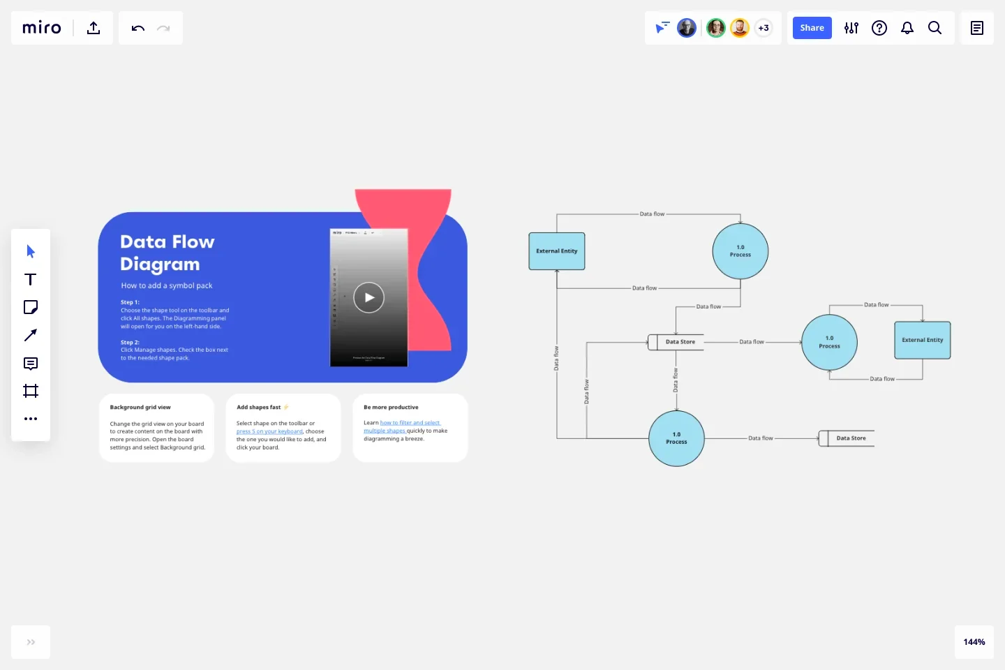
Miro's Data Flow Diagram template can help you get quick started with your own DFD. You can build your data flow diagram with shapes, which will visually show the steps or actors of your system, and use the connector lines with arrows to show the flow of your system.
Data flow diagrams are not just diagrams; they are the language of systems and processes. Understanding and utilizing data flow diagram examples in your field can lead to improved efficiency, clearer communication, and better decision-making. Be sure to use a Data Flow Diagram tool to map out and analyze your systems in a visual and clear way.
Discover more
What is a data flow diagram
Data flow diagrams vs flowcharts
Data migration process flow diagrams for streamlining transitions
Get on board in seconds
Join thousands of teams using Miro to do their best work yet.
A Beginner's Guide to Data Flow Diagrams
Published: September 06, 2023
Ask any professional athlete or business executive how they became successful, and they’ll tell you they mastered a process. By figuring out which habits led to success and which didn’t, they improved their efficiency and productivity.

But implementing a process into a business, department, or even a team is a completely different animal than honing your personal process. With so many moving parts, how do you track and refine each aspect of your business process?
![dfd case study with solution Download Now: An Introduction to Data Visualization for Marketers [Free Guide]](https://no-cache.hubspot.com/cta/default/53/6ecf26a9-faff-4c16-a2d4-b70751ce8b65.png)
Data flow diagrams provide a straightforward, efficient way for organizations to understand, perfect, and implement new processes or systems. They’re visual representations of your system, making it easy to understand and prune.
Before we dive into how data flow diagrams can help refine any of your business systems or processes, let’s go over what exactly it is.
What is a data flow diagram (DFD)?
A data flow diagram (DFD) is a visual representation of the information flow through a process or system. DFDs help you better understand process or system operations to discover potential problems, improve efficiency, and develop better processes. They range from simple overviews to complex, granular displays of a process or system.
An Introduction to Data Visualization
Learn how to design compelling charts & graphs that are easy to understand, including:
- Tools and Software for Data Visualization
- Data Types, Relationships, and Formats
- How to Effectively Visualize Data
- A History of Data Visualization
Download Free
All fields are required.
You're all set!
Click this link to access this resource at any time.
The Benefits of Data Flow Diagrams
DFDs are visual representations that can help almost anyone grasp a system‘s or process’ logic and functions. Aside from being accessible, they provide much-needed clarity and improve productivity. Here's how.
Accessibility
Because visual information is easier to digest, DFDs typically explain complex concepts better than blocks of text can.
Visual presentations of how a process works can also hold people's attention longer — making it easier to retain the information.
DFDs clarify the systems and processes necessary for your team to do their best work. Whether implementing a new company-wide system or refining a department's existing process, a DFD gets you and your team on the same page.
Creating DFDs will give you clarity about business operations, too. A clearer understanding enables you to refine and track your business processes with less friction.
Productivity
The accessibility and clarity created with DFDs will leave less room for error. Your team will better master systems and processes because they understand them.
Greater understanding — paired with a repeatable process — will likely boost team effectiveness and productivity.
On a broader level, DFDs can help you streamline your business operations. When mapping out your processes, you‘ll gain insights into what does and doesn’t work.
These insights help boost you and your team's productivity. As a bonus, you can share any best practices across departments.
Data Flow Diagram Symbols
Before using a DFD, you need to know the symbols used to describe it.
Data flow diagram symbols are standardized notations, like rectangles, circles, arrows, and short-text labels. These symbols represent a system’s data flow direction, inputs, outputs, storage points, and sub-processes.
Four common methods of notation are used in DFDs: Yourdon & De Marco, Gene & Sarson, SSADM, and Unified.
All use the same labels and similar shapes to represent the four main elements of a DFD — external entity, process, data store, and data flow.


Perfecting Your Process
While there’s no such thing as a “perfect” data flow diagram, continued practice can help streamline the process and offer critical insight into what’s working, what isn’t, and where your business can make impactful improvements.
Your best bet? Remember the rule: Keep it simple. Start with context, build out connected processes, and repeat as needed to map key connections, flows, and entities across your organization.
![dfd case study with solution Blog - Data Visualization [List-Based]](https://no-cache.hubspot.com/cta/default/53/2f02d8fe-c9b0-4078-a3ae-5831c892fbd0.png)
Don't forget to share this post!
Related articles.
![dfd case study with solution The Top Search Engines in 2024 [Including 17 Google Alternatives]](https://www.hubspot.com/hubfs/other%20search%20engines%20header%20image%20.jpg)
The Top Search Engines in 2024 [Including 17 Google Alternatives]

Permalinks: What They Are & How to Structure Them for Max SEO Value

What is Website Architecture? 8 Easy Ways to Improve Your Site Structuring

Image Alt Text: What It Is, How to Write It, and Why It Matters to SEO
Diving Deep Into Technical SEO for Ecommerce (My Takeaways)

How Your JavaScript Can Benefit Your SEO

Everything You Need to Know About Google Search Essentials (formerly Google Webmaster Guidelines)

Duplicate Content Issues on Your Website? Easy Ways to Find and Fix Them

The Ultimate Guide to Google Search Console in 2024

Does Google Think Your Website Is Spam?
How to design compelling charts & graphs that are easy to understand
Marketing software that helps you drive revenue, save time and resources, and measure and optimize your investments — all on one easy-to-use platform
- Software Engineering Tutorial
- Software Development Life Cycle
- Waterfall Model
- Software Requirements
- Software Measurement and Metrics
- Software Design Process
- System configuration management
- Software Maintenance
- Software Development Tutorial
- Software Testing Tutorial
- Product Management Tutorial
- Project Management Tutorial
- Agile Methodology
- Selenium Basics
What is DFD(Data Flow Diagram)?
Data Flow Diagram (DFD) represents the flow of data within information systems. Data Flow Diagrams (DFD) provide a graphical representation of the data flow of a system that can be understood by both technical and non-technical users. The models enable software engineers, customers, and users to work together effectively during the analysis and specification of requirements.
Table of Content
What is Data Flow Diagram (DFD)?
Characteristics of data flow diagram (dfd).
- Physical and Logical data flow diagrams (DFDs)
Components of Data Flow Diagrams (DFD)
Levels of data flow diagram (dfd), rules for data flow diagram (dfd), advantages of data flow diagram (dfd), disadvantages of data flow diagram (dfd), how to draw data flow diagram, frequently asked questions (faqs) related to data flow diagram (dfd).
DFD is the abbreviation for Data Flow Diagram . The flow of data in a system or process is represented by a Data Flow Diagram (DFD). It also gives insight into the inputs and outputs of each entity and the process itself. Data Flow Diagram (DFD) does not have a control flow and no loops or decision rules are present. Specific operations, depending on the type of data, can be explained by a flowchart. It is a graphical tool, useful for communicating with users, managers and other personnel. it is useful for analyzing existing as well as proposed systems.
It should be pointed out that a DFD is not a flowchart. In drawing the DFD, the designer has to specify the major transforms in the path of the data flowing from the input to the output. DFDs can be hierarchically organized, which helps in progressively partitioning and analyzing large systems.
It provides an overview of
- What data is system processes.
- What transformation are performed.
- What data are stored.
- What results are produced , etc.
Data Flow Diagram can be represented in several ways. The Data Flow Diagram (DFD) belongs to structured-analysis modeling tools. Data Flow diagrams are very popular because they help us to visualize the major steps and data involved in software-system processes.
Below are some characteristics of Data Flow Diagram (DFD):
- Graphical Representation : Data Flow Diagram (DFD) use different symbols and notation to represent data flow within system. That simplify the complex model.
- Problem Analysis: Data Flow Diagram ( DFDs) are very useful in understanding a system and can be effectively used during analysis. Data Flow Diagram (DFDs) are quite general and are not limited to problem analysis for software requirements specification.
- Abstraction : Data Flow Diagram (DFD) provides a abstraction to complex model i.e. DFD hides unnecessary implementation details and show only the flow of data and processes within information system.
- Hierarchy : Data Flow Diagram (DFD) provides a hierarchy of a system. High- level diagram i.e. 0-level diagram provides an overview of entire system while lower-level diagram like 1-level DFD and beyond provides a detailed data flow of individual process.
- Data Flow : The primary objective of Data Flow Diagram (DFD) is to visualize the data flow between external entity, processes and data store. Data Flow is represented by an arrow Symbol.
- Ease of Understanding : Data Flow Diagram (DFD) can be easily understand by both technical and non-technical stakeholders.
- Modularity : Modularity can be achieved using Data Flow Diagram (DFD) as it breaks the complex system into smaller module or processes. This provides easily analysis and design of a system.
Types of Data Flow Diagram (DFD)
There are two types of Data Flow Diagram (DFD)
- Logical Data Flow Diagram
- Physical Data Flow Diagram
Logical Data Flow Diagram (DFD)
Logical data flow diagram mainly focuses on the system process. It illustrates how data flows in the system. Logical Data Flow Diagram (DFD) mainly focuses on high level processes and data flow without diving deep into technical implementation details. Logical DFD is used in various organizations for the smooth running of system. Like in a Banking software system, it is used to describe how data is moved from one entity to another.
Logical Data Flow Diagram of Online Grocery Store Physical Data Flow Diagram
Physical data flow diagram shows how the data flow is actually implemented in the system. In the Physical Data Flow Diagram (DFD), we include additional details such as data storage, data transmission, and specific technology or system components. Physical DFD is more specific and close to implementation.
.webp)
Physical Data Flow Diagram of online Grocery Store
The Data Flow Diagram has 4 components :
- Process: Input to output transformation in a system takes place because of process function. The symbols of a process are rectangular with rounded corners, oval, rectangle or a circle. The process is named a short sentence, in one word or a phrase to express its essence
- Data Flow: Data flow describes the information transferring between different parts of the systems. The arrow symbol is the symbol of data flow. A relatable name should be given to the flow to determine the information which is being moved. Data flow also represents material along with information that is being moved. Material shifts are modeled in systems that are not merely informative. A given flow should only transfer a single type of information. The direction of flow is represented by the arrow which can also be bi-directional.
- Warehouse (Data Store) : The data is stored in the warehouse for later use. Two horizontal lines represent the symbol of the store. The warehouse is simply not restricted to being a data file rather it can be anything like a folder with documents, an optical disc, a filing cabinet. The data warehouse can be viewed independent of its implementation. When the data flow from the warehouse it is considered as data reading and when data flows to the warehouse it is called data entry or data updating.
- Terminator (External Entity): The Terminator is an external entity that stands outside of the system and communicates with the system. It can be, for example, organizations like banks, groups of people like customers or different departments of the same organization, which is not a part of the model system and is an external entity. Modeled systems also communicate with terminator.

Basic Structure of Data Flow Diagram (DFD)
What symbols and notations are used to represent Components of DFD?
In Data-Flow Diagrams (DFDs), symbols and notations vary depending on the methodology being used. Here’s a summary of symbols and notations commonly associated with each methodology:
The different methodologies or approaches used for creating Data-Flow Diagrams (DFDs) are:
- Gane and Sarson
- Yourdon and De Marco
Each methodology provides its own set of guidelines, symbols, and notations for representing system components and their interactions.

Data Flow Diagram Methods and Symbol
Data Flow Diagram (DFD) uses hierarchy to maintain transparency thus multilevel Data Flow Diagram (DFD’s) can be created. Levels of Data Flow Diagram (DFD) are as follows:
0-level DFD
It is also known as a context diagram. It’s designed to be an abstraction view, showing the system as a single process with its relationship to external entities. It represents the entire system as a single bubble with input and output data indicated by incoming/outgoing arrows.
Level 0 of Railway Reservation System 1-Level DFD
This level provides a more detailed view of the system by breaking down the major processes identified in the level 0 DFD into sub-processes. Each sub-process is depicted as a separate process on the level 1 DFD. The data flows and data stores associated with each sub-process are also shown. In 1-level DFD, the context diagram is decomposed into multiple bubbles/processes. In this level, we highlight the main functions of the system and breakdown the high-level process of 0-level DFD into subprocesses.
Level 1 DFD of Railway Reservation System 2-level DFD
This level provides an even more detailed view of the system by breaking down the sub-processes identified in the level 1 DFD into further sub-processes. Each sub-process is depicted as a separate process on the level 2 DFD. The data flows and data stores associated with each sub-process are also shown.
Following are the rules of DFD:
- Terminator or External Entity to Process
- Process to Terminator or External Entity
- Process to Data Store
- Data Store to Process
- Process to Process
- Terminator or External Entity to Terminator or External Entity
- Terminator or External Entity to Data Store
- Data Store to Terminator or External Entity
- Data Store to Data Store
- It helps us to understand the functioning and the limits of a system.
- It is a graphical representation which is very easy to understand as it helps visualize contents.
- Data Flow Diagram represent detailed and well explained diagram of system components.
- It is used as the part of system documentation file.
- Data Flow Diagrams can be understood by both technical or nontechnical person because they are very easy to understand.
- At times Data Flow Diagram (DFD) can confuse the programmers regarding the system.
- Data Flow Diagram takes long time to be generated, and many times due to this reasons analysts are denied permission to work on it.
Following are the steps to Draw Data Flow Diagram
- Understand the System
- Identify External Entities
- Identify Processes
- Identify Data Stores
- Use Standard Symbols
- Create Level 0 Diagram
- Based on Complexity Draw Further Level Diagram like Level 1, 2 and so on.
- Identify Data Flows:
- Number Processes and Data Stores
- Review and Validate
Data Flow Diagram ( DFD) are visual maps that provides a clear understanding of how information moves within a information system. Data Flow Diagrams (DFD) consist of four component i.e. Processes that represent system’s functionality, External Entities that represent the end users, data store that represent database or data ware house and data flow that represent how data are flow among these three components. DFD help everyone, from computer experts to regular users, as it provide a clear understanding of how a system works and how different parts of it interact. By using DFDs, people can work together effectively to analyze, design, and communicate about systems.
What are the 4 components of DFD?
Four Components of DFD are: Process Data Flow Data Store External Entity
What are the symbols used in DFD?
Symbols Used in DFD are standardized notations, like rectangles, circles, arrows, and short-text labels.
What are the levels of DFD?
Levels in DFD are numbered 0, 1, 2 or beyond.
Is flowchart a DFD?
No, Both are different. A flowchart illustrates the sequence of steps or actions within a process, detailing the logic and decision points, while a Data-Flow Diagram (DFD) focuses on representing the flow of data within a system, showing how data moves between processes, data stores, and external entities without specifying the sequence of actions.
Please Login to comment...
Similar reads.
- Computer Subject
- Software Engineering
- System Design
- Write From Home
Improve your Coding Skills with Practice
What kind of Experience do you want to share?

- Demo Videos
- Interactive Product Tours
- Request Demo
What is Data Flow Diagram (DFD)? How to Draw DFD?
Compatible edition(s): Enterprise , Professional , Standard , Modeler
- January 27, 2012
- Views: 2,221,927
What is a data flow diagram (DFD)?
A picture is worth a thousand words. A Data Flow Diagram (DFD) is a traditional way to visualize the information flows within a system. A neat and clear DFD can depict a good amount of the system requirements graphically. It can be manual, automated, or a combination of both.
It shows how information enters and leaves the system, what changes the information and where information is stored. The purpose of a DFD is to show the scope and boundaries of a system as a whole. It may be used as a communications tool between a systems analyst and any person who plays a part in the system that acts as the starting point for redesigning a system.
It is usually beginning with a context diagram as level 0 of the DFD diagram, a simple representation of the whole system. To elaborate further from that, we drill down to a level 1 diagram with lower-level functions decomposed from the major functions of the system. This could continue to evolve to become a level 2 diagram when further analysis is required. Progression to levels 3, 4 and so on is possible but anything beyond level 3 is not very common. Please bear in mind that the level of detail for decomposing a particular function depending on the complexity that function.
DFD Diagram Notations
Now we'd like to briefly introduce to you a few diagram notations which you'll see in the tutorial below.
External Entity
An external entity can represent a human, system or subsystem. It is where certain data comes from or goes to. It is external to the system we study, in terms of the business process. For this reason, people used to draw external entities on the edge of a diagram.
.png)
What will we do in this tutorial?
In this tutorial, we will show you how to draw a context diagram, along with a level 1 diagram.
Note: The software we are using here is Visual Paradigm . You are welcome to download a free 30-day evaluation copy of Visual Paradigm to walk through the example below. No registration, email address or obligation is required.
How to Draw Context Level DFD?
- To create new DFD, select Diagram > New from the toolbar.
- In the New Diagram window, select Data Flow Diagram and click Next .
- Enter Context as diagram name and click OK to confirm.
How to Draw Level 1 DFD?
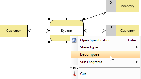
- The data stores and/or external entities connected to the selected process ( System ) would be referred to in the level 1 DFD. So when you are prompted to add them to the new diagram, click Yes to confirm. Note: The new DFD should look very similar to the Context diagram initially. Every element should remain unchanged, except that the System process (from which this new DFD decomposes) is now gone and replaced by a blank space (to be elaborated).
- Rename the new DFD. Right-click on its background and select Rename... . In the diagram's name box, enter Level 1 DFD and press ENTER .
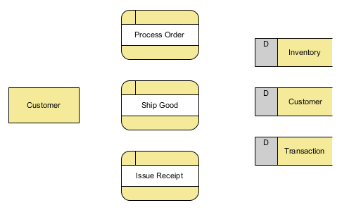
Wiring with connection lines for data flows
The remaining steps in this section are about connecting the model elements in the diagram. For example, Customer provides order information when placing an order for processing.
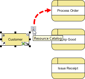
How to Improve a DFD's Readability?
The completed diagram above looks a bit rigid and busy. In this section, we are going to make some changes to the connectors to increase readability.
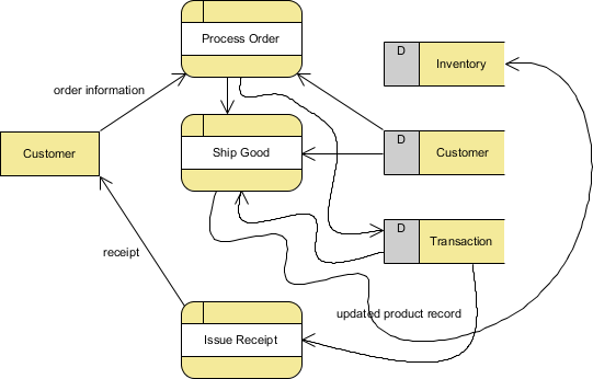
More DFD Examples
The list below directs you to various Data Flow Diagram examples that cover different businesses and problem domains. Some of them consist of the use of multiple context levels.
- Customer Service System
- Food Ordering System
- Securities Trading
- Supermarket App
- Vehicle Maintenace Depot
- Video Rental Store
- Order-Processing.vpp
- Order-Processing_result.vpp
Readers of this tutorial also read
- Data Flow Diagram: Examples - Food Ordering System
- How to Write Effective Use Cases?
- How to Develop As-Is and To-Be Business Process?
- How to Model Relational Database Design with ERD?
- How to Draw UML Diagrams in NetBeans?
- Enterprise Architecture
- TOGAF ADM Software: How to Use?
- Drawing ArchiMate Diagram
- Design & Modeling
- Problem Desc. to Model
- Creating Activity Diagram
- Creating State Machine Diagram
- Creating Component Diagram
- Creating Deployment Diagram
- Cause and Effect Diagram
- Drawing Timing Diagram
- Class Diagram in Java, C# and VB
- Animating Activity Diagram
- Drawing Profile Diagram
- Attach file reference to model
- Using sub-diagrams
- UML Package Diagram
- Mult-party service in SoaML
- Drawing SoaML Diagram
- Stereotypes and tagged values
- Define custom element properties
- Merge actors in use case diagram
- Numbering sequence messages
- Using Textual Analysis
- Seq. Diagram duration constraint
- Fill-in UML state's body
- Edit attribute's initial value
- Drawing Sequence Diagram
- Test cases for SysML requirement
- Customize requirement types
- Drawing Communication Diagram
- Develop Sequence Diagram with keybaord
- Abstract Factory Pattern Tutorial
- Factory Method Pattern Tutorial
- Builder Pattern Tutorial
- Prototype Pattern Tutorial
- Singleton Pattern Tutorial
- Adapter Pattern Tutorial
- Proxy Pattern Tutorial
- Composite Pattern Tutorial
- Bridge Pattern Tutorial
- Decorator Pattern Tutorial
- Flyweight Pattern Tutorial
- Facade Pattern Tutorial
- Command Pattern Tutorial
- Chain of Responsibility Pattern Tutorial
- Interpreter Pattern Tutorial
- Iterator Pattern Tutorial
- Observer Pattern Tutorial
- Memento Pattern Tutorial
- Mediator Pattern Tutorial
- Template Pattern Tutorial
- Strategy Pattern Tutorial
- State Pattern Tutorial
- Visitor Pattern Tutorial
- Create BPMN diagram
- Business process modeling
- Business Process Mapping
- Creating BPMN diagram
- Using Data Object in BPMN
- BPD Example - Leave Application
- BPMN Intro I
- BPMN Intro II - Swimlanes
- BPMN Intro III - Flow/Connectors
- BPMN Intro IV - Data & Artifacts
- Develop As-is & To-be BPD
- Working procedures of BP tasks
- Link data object with ERD entity
- Animate BPMN business process
- BPMN process simulation
- Import Bizagi project
- Use stereotype in EPC Diagram
- Secondary pools for BPMN task
- Drill-down a BPMN sub-process
- Process simulation example
- Drawing BPMN Conversation Diagram
- BPMN 2.0 BPD
- Create Circuit Diagram
- Create Venn Diagram
- Create Floor Plan
- Create Network Diagram
- Flowchart Tutorial
- DFD Example - Customer Service
- DFD Example - Food Ordering
- DFD Example - Securities Trading
- DFD Example - Supermarket App
- DFD Example - Vehicle Main. Depot
- DFD Example - Video rental
- Functional decomposition in DFD
- Data Flow Diagram Tutorial
- Using Storyboard with User Story
- Wireframe for Android apps design
- Product Breakdown Structure
- Work Breakdown Structure
- Radar Chart tutorial
- Creating Fishbone Diagram
- Customer Journey Mapping (CJM)
- Create stereotyped model element
- Bookmark shapes
- Select shapes with Handi-Selection
- Diagram annotation with layer
- Diagram Info Shape
- Appearance of stereotyped shape
- Tidy-up diagram with Sweeper/Magnet
- Convert model element's type
- Import Visio drawing as stencil
- Create Mind Map
- What is Mind Mapping? How to Draw a Mind Map?
- Edit model elements with Excel
- Associat parent & subdiagram flow
- Listing elements with grid
- Ad-hoc idea capturing with Brainstorm Diagram
- Identify use cases from BP process
- Refactor classes to ref. project
- Create project reference
- Create nickname for multi-name set
- Animating Sequence Diagram
- Organize domaing and impl. model
- Align business goal & logic with Decision Table
- Decision Table in-action
- Discover business logic with Decision Table
- Sensible business with Decision Table
- Decision Table in EA
- Using Matrix Diagram
- Using Analysis Diagram
- SWOT Analysis Tutorial
- Five Forces Analysis Tutorial
- Agile Requirements
- Add classes to flow-of-events
- Advanced use case flow-of-events
- Test procedures in flow-of-events
- Produce use cases from BPD
- Agile Scrum Tutorial
- User Story - Confirmation items
- Mapping BPMN with User Stories
- Using Storyboard
- Using tag on user story
- Model business goals of a system
- Using UeXceler - YouTube example
- Writing effective use case
- Generate Seq. Diagram from user story
- Generate Activity Diagram from user story
- Code & DB
- Generate ERD from RedShift DB
- Generate RedShift DB from ERD
- Compare logical and physical ERD
- Design & generate SQL Server DB
- Generate ERD from DDL
- Generate DB spec. from DB
- Keep data dict. in-sync with ERD
- Database design with ERD
- Edit nullable column in ERD
- Insert sample data into ERD
- Model RDBMS with ERD
- Generate class diagram from ERD
- Oracle DB design tool
- Oracle DB design with ERD
- Mass edit DB design with Excel
- Oracle DB reverse engineering
- Generate DB change script
- Compare DB schemas visually
- Define custom implementations for ORM Class
- Hibernate ORM in Eclipse
- Using Hibernate Criteria
- Generate Hibernate mapping for Oracle DB
- Java round-trip engineering
- C++ round-trip engineering
- Generate code from State Machine
- REST API - Twitter example
- REST API - Simple Reg. example
- Form Seq. Diagram from Java
- Hibernate ORM in NetBeans
- Visual modeling in NetBeans
- UML modeling in Eclipse
- C# round-trip engineering
- Generate C# from UML in VS
- Generate Java from UML classes in NetBeans
- Keep code and UML model in-sync in Eclipse
- Task Management Guide
- Share & review process design
- Share & discuss BPD online
- Prioritize tasks in Tasifier
- Storing reference files in project
- View and Revert changes with Visual History
- Communicate process design with PostMania
- Communicate software design with PostMania
- Concurrent process modeling
- Create Use Case report
- Create software req. spec.
- Customize Doc. Composer templates
- Maintain project of glossary
- Maintain glossary for terms
- Build glossary from class model
- Extract glossary from BPMN process
- Extract glossary terms from shapes' name
- Track occurrence of glossary terms
- Derive use case from terms
- Derive data dict. from Textual Analysis
- Generate RACI from BPMN
- Customize RACI chart
- Develop Visual Paradigm plug-in
- Change application's font settings
- Hide-away toolbar buttons

While teaching an information systems analysis and design course, I reviewed over 20 CASE tools which supported UML. Visual Paradigm was by far the most intuitive and comprehensive.
Professor Melody Y. Ivory-Ndiaye
University of Washington, Seattle
Turn every software project into a successful one.
We use cookies to offer you a better experience. By visiting our website, you agree to the use of cookies as described in our Cookie Policy .
© 2024 by Visual Paradigm. All rights reserved.
- Privacy statement
How to Make a Data Flow Diagram
What are your dfd needs, i want to make my own dfd in lucidchart., i want to make a dfd from a lucidchart template..
Businesses use data flow diagrams every day to analyze existing systems to see where roadblocks exist and to create new business processes. A data flow diagram (DFD) illustrates the flow and transformation of data for a particular business process. It’s a visual representation of how data flows through a system, so you can clearly see where the data comes from, where it goes, and how it gets stored. Learn how you can make a DFD with Lucidchart in just 10 steps.
6 minute read
Want to make a DFD of your own? Try Lucidchart. It's quick, easy, and completely free.
Elements of a data flow diagram
There are standard data flow diagram symbols used to represent different parts of the system. For example, you’ll use one shape to represent an external entity and another symbol for a process. To learn more about data flow diagram symbols, check out our guide here . Here are the symbols you’ll need to use to create a DFD:
| are a circle or a square with a horizontal line across the top. A process is a business activity where the manipulation and transformation of data occurs. Something happens to the data during a process. | |
| represent how the data flows. Use the type of data that is moving through the system as the name for the arrow. | |
| is shown as a square. An external entity can be a person, system, or application. It’s where data starts or ends. | |
| are rectangles (sometimes they have a vertical line in the symbol), and they show where required or produced data related to the process is stored. |
10 simple steps to draw a data flow diagram online with Lucidchart
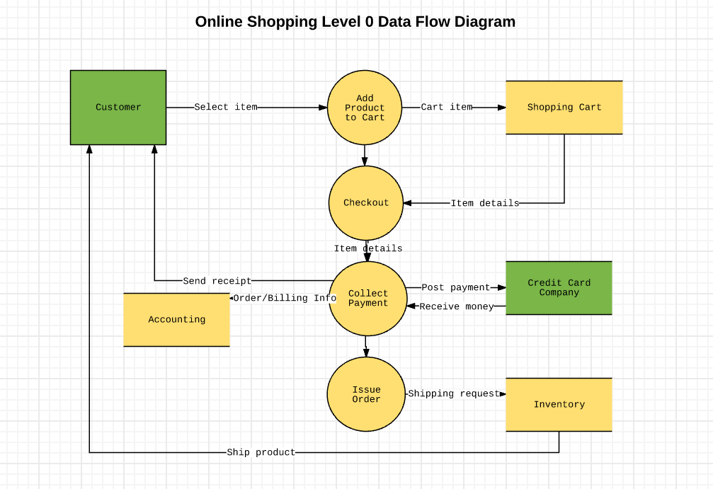
Now that you know what makes up a data flow diagram, let’s see how easy it is to make one using our powerful, online tool. We provide a ton of templates to use as a starting point. In this how-to, we’re going to create a Level 0 DFD for an online shopping experience. Log in to your account (if you don’t have one, sign up to try Lucidchart free for a week) and follow the steps below to make a DFD.
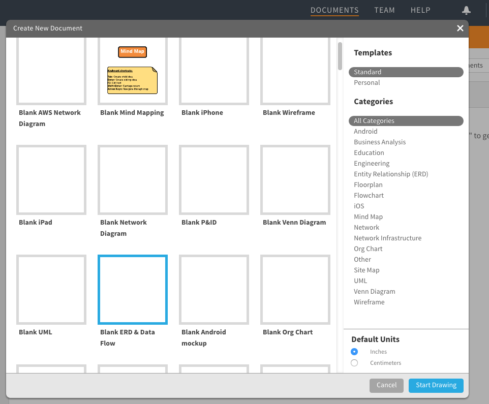
1. Select a data flow diagram template
In the Documents section, click on the orange +Document button and double-click on the Blank ERD & Data Flow diagram.
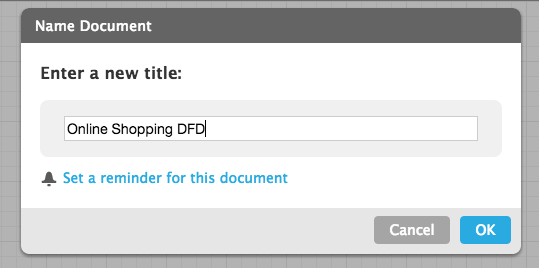
2. Name the data flow diagram
Click on the Blank ERD & Data Flow header in the top left corner of the screen. A pop-up screen opens, type the name of your diagram in the text box and click OK. The name of your DFD appears in the top left corner of the screen.
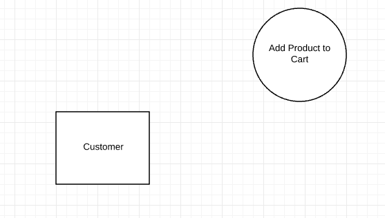
3. Add an external entity that starts the process
In the left column of the screen, you’ll notice a lot of shapes and symbols. We’ve already created the four symbols you’ll need to make a DFD. You can also add images to the diagram. Scroll through the list of symbols until you get to the bottom and see the heading Data Flow.
These are all the DFD symbols you need. (Note: Mouse over each shape to see what they represent: process, data stores, data flow, and external entities). We have symbols for Yourdon and Coad, Yourdon and DeMarco, and Gane and Sarson methods. Click and hold External Entity and drag it onto the workspace.
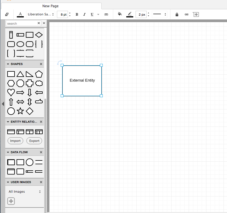
Click the highlighted text in the box and type the name of the external entity. For our example, we’re typing “customer.” You can use the curved arrow in the top left corner of the square to rotate the symbol. Delete a symbol by clicking it and pressing delete on your keyboard.
4. Add a Process to the DFD
Click and hold on a process symbol and drag it to where you want it on the workspace. Type the name of the process. We’re calling this process “add product to cart.”
5. Add a data store to the diagram
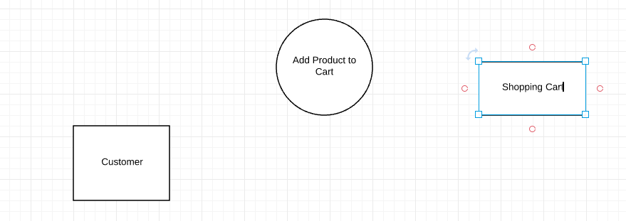
Click and hold on a data store symbol and drag it to where you want it on the workspace. Type the data store name. We’re naming ours “shopping cart.”
6. Continue to add items to the DFD
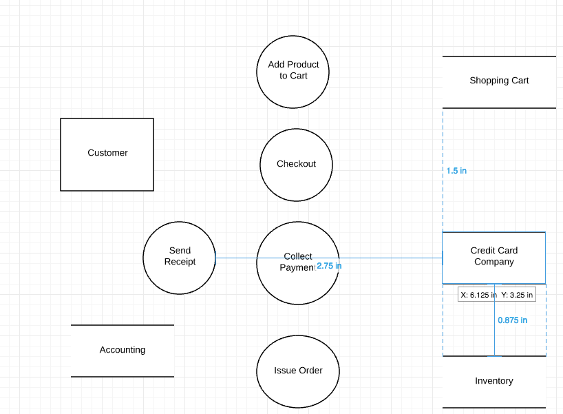
Drag-and-drop the appropriate symbols to add all the external entities, processes, and data stores to your diagram. Move symbols around by clicking and holding on them, and then drag them to a new location. Click on a symbol to resize it, then click and hold the blue box in one of the corners and drag the corner to make the shape bigger or smaller. Use the background graph as a guide for alignment and sizing.
7. Add data flow to the DFD
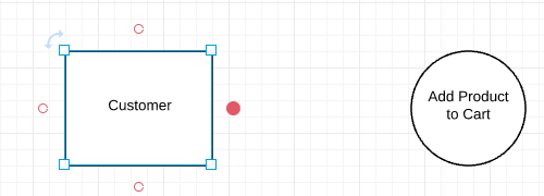
Double-click on an entity, process, or data store, and then click and hold one of the orange circles and drag the line to the appropriate symbol.
8. Name the data flow
Add a name to describe the data flow by double-clicking on the arrow line. An option to type text will appear, type the data flow name.

9. Customize the DFD with colors and fonts
Once you have the basic design of your diagram, you can add colors to symbols, change fonts, and adjust arrows. Here’s how to:
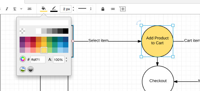
- Add colors to symbols: Click on a symbol on the diagram and then click the color-fill icon and choose a color.
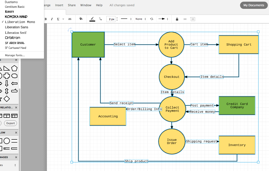
- Change the font: Choose Select All from the Edit option in the menu. Click the font box, choose a new font, and click it. All text in the diagram will be updated. You can use the other shortcuts (font color, size, bold, italic, underline, and alignment) to customize the font even more.
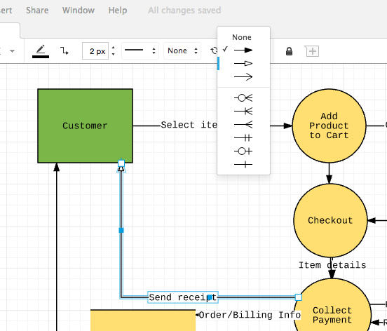
- Adjust arrow style: Click an arrow to select it. Next, click the arrow icon in the menu bar and choose one of the nine other styles.
10. Add a title and share your data flow diagram
At the top of the symbols column, you’ll see a large letter T. Click it and drag it to where you want to add a title to the diagram. Type the title, and if you’d like to, adjust the font and type size using the shortcut keys at the top of the screen.
The easiest way to make a data flow diagram online
There you have it, the easiest way to make a data flow diagram online. Since Lucidchart is a web-based app, your diagram is automatically saved, and you can access it virtually anywhere you have an Internet connection. When you share your DFD with colleagues, you’ll never have to wonder if they can open the file or access it. Best of all, if you give them permission to edit they can make changes to the DFD and add comments. Sign up for a free trial and see how easy it is to use Lucidchart.
Helpful Resources
- Data Flow Diagram Symbols
- What is a Data Flow Diagram
Now you're ready to start building professional data flow diagrams with Lucidchart.
Thank you for visiting nature.com. You are using a browser version with limited support for CSS. To obtain the best experience, we recommend you use a more up to date browser (or turn off compatibility mode in Internet Explorer). In the meantime, to ensure continued support, we are displaying the site without styles and JavaScript.
- View all journals
- Explore content
- About the journal
- Publish with us
- Sign up for alerts
- Open access
- Published: 08 August 2024
Comprehensive study on the efficiency of vertical bifacial photovoltaic systems: a UK case study
- Ghadeer Badran 1 &
- Mahmoud Dhimish 1
Scientific Reports volume 14 , Article number: 18380 ( 2024 ) Cite this article
217 Accesses
Metrics details
- Photovoltaics
- Renewable energy
- Solar energy
This paper presents the first comprehensive study of a groundbreaking Vertically Mounted Bifacial Photovoltaic (VBPV) system, marking a significant innovation in solar energy technology. The VBPV system, characterized by its vertical orientation and the use of high-efficiency Heterojunction cells, introduces a novel concept diverging from traditional solar panel installations. Our empirical research, conducted over a full year at the University of York, UK, offers an inaugural assessment of this pioneering technology. The study reveals that the VBPV system significantly outperforms both a vertically mounted monofacial PV (VMPV) system and a conventional tilted monofacial PV (TMPV) system in energy output. Key findings include a daily power output increase of 7.12% and 10.12% over the VMPV system and an impressive 26.91% and 22.88% enhancement over the TMPV system during early morning and late afternoon hours, respectively. Seasonal analysis shows average power gains of 11.42% in spring, 8.13% in summer, 10.94% in autumn, and 12.45% in winter compared to the VMPV system. Against the TMPV system, these gains are even more substantial, peaking at 24.52% in winter. These results underscore the VBPV system's exceptional efficiency in harnessing solar energy across varied environmental conditions, establishing it as a promising and sustainable solution in solar energy technology.
Integration of two-dimensional materials-based perovskite solar panels into a stand-alone solar farm
Sustainability pathways for perovskite photovoltaics
Efficiency limits of concentrating spectral-splitting hybrid photovoltaic-thermal (PV-T) solar collectors and systems
Introduction.
Solar photovoltaic (PV) technology has become a cornerstone of the renewable energy revolution, offering a clean, sustainable solution to the world's growing energy demands 1 . At its core, solar PV harnesses the sun's energy, converting it directly into electricity through semiconducting materials. This technology has traditionally been dominated by monofacial PV modules 2 , which collect sunlight from a single surface facing the sun. However, as the need for more efficient and cost-effective energy solutions intensifies, the evolution of solar PV has given rise to the bifacial module 3 , 4 —a novel approach to solar energy capture that promises to redefine the efficiency standards of solar energy systems.
Bifacial PV modules, as shown in Fig. 1 , are designed to capture sunlight on both their front and rear surfaces, utilizing direct sunlight and the light that reaches the rear surface through ground reflection and diffuse albedo 5 , 6 . Despite relying on silicon cells with the same spectral response as monofacial PV modules, the dual-sided design of bifacial modules allows them to significantly enhance energy yield by absorbing reflected and diffused light from surrounding surfaces 7 . This design is particularly beneficial in environments with high ground reflectivity or engineered ground covers to increase reflectivity 8 .

Illustration of bifacial PV system operation. The arrows indicate the different pathways of sunlight: yellow arrows represent direct sunlight hitting the front surface and the ground, orange arrows indicate the sunlight reflected from the ground hitting the rear surface, and red arrows depict the diffuse sunlight captured by both the front and rear surfaces 11 .
The evolution of bifacial PV modules represents more than just an incremental improvement in solar technology; it signifies a paradigm shift in how solar energy is harvested. Unlike traditional monofacial systems 9 that are limited by their unidirectional light capture, bifacial systems exploit the full spectrum of solar irradiance. This is achieved through a combination of advanced cell technology and innovative panel designs, which optimize light absorption from multiple angles 10 . The result is a marked increase in energy production per unit area, a critical factor in maximizing the efficiency of solar installations.
Moreover, the integration of bifacial PV technology aligns seamlessly with the global push towards sustainable development. By enhancing the power output of solar installations without the need for additional land, bifacial PV systems contribute to a more efficient use of resources. This efficiency is not confined to optimal conditions; bifacial modules demonstrate resilience in a variety of environmental settings 11 , 12 , including regions with lower solar irradiance and urban landscapes 13 where space and light conditions are constrained.
The significance of bifacial PV modules extends beyond their operational advantages. Their deployment has profound implications for energy policy, economic planning, and environmental strategy. By offering a more versatile and powerful solution for solar energy generation, bifacial PV systems can accelerate the transition to renewable energy sources, reduce dependency on fossil fuels, and mitigate the impacts of climate change.
In the realm of bifacial PV technology, various configurations have been explored to maximize the efficiency and adaptability of solar energy systems. These include vertical, tilted, and other innovative arrangements, each with its unique operational characteristics and applications. Vertical bifacial PV systems: These systems involve panels mounted in a vertical orientation. The key advantage of vertical bifacial PV is its ability to capture sunlight effectively throughout the day, from both sides of the panel 14 . This configuration is particularly beneficial in higher latitudes where the sun is lower in the sky 15 . Vertical systems are also less prone to accumulating dirt and debris, reducing maintenance requirements. Current research indicates that vertical bifacial systems can achieve significant energy gains in urban environments, where space is limited, and in regions with considerable diffuse light 16 .
Tilted bifacial PV Systems: Tilted systems are more traditional, where panels are installed at an angle to maximize exposure to direct sunlight. Bifacial panels in this configuration can capture reflected light from the ground or any reflective surface below. The optimal tilt angle is a subject of ongoing research, with studies 17 , 18 , 19 suggesting that slight adjustments in the tilt can lead to substantial increases in energy capture, particularly in areas with high ground albedo. And finally, tracking bifacial PV systems: These are dynamic systems where panels can adjust their orientation to follow the sun’s path 20 . This tracking capability, combined with bifacial technology, maximizes solar energy capture throughout the day. Research 21 , 22 shows that tracking bifacial systems offer the highest yield, especially in regions with high direct sunlight, making them a promising solution for large-scale solar farms.
Each of these configurations brings unique advantages and challenges, shaping the current research and development in the field of bifacial PV technology. Studies are continually underway to optimize the design, installation, and operational parameters of these systems. This includes investigating factors like the optimal distance between rows of panels 23 to prevent shading, the effect of different surfaces 24 and materials on light reflection, and the integration of smart technologies for performance monitoring and optimization. Furthermore, the performance of bifacial PV systems is significantly influenced by shading and the reflective properties of surrounding surfaces. Shading can reduce the overall efficiency by blocking sunlight from reaching both the front and rear surfaces of the panels. Detailed models of shading and illumination, such as those reported by 25 and 26 , provide comprehensive insights into these effects. In 25 the authors demonstrated that partial shading could lead to substantial reductions in energy output, especially in high-density installations. Further work by 26 explored the impacts of various surface materials and albedo on bifacial PV performance, showing that engineered surfaces with higher reflectivity can enhance energy yield by increasing the diffuse light captured by the rear surface of the panels. These models underscore the importance of considering shading and surface properties in the design and deployment of bifacial PV systems to optimize their performance.
The evolution of bifacial PV modules represents more than just an incremental improvement in solar technology; it signifies a paradigm shift in how solar energy is harvested. Unlike traditional monofacial systems that are limited by their unidirectional light capture, bifacial systems exploit the full spectrum of solar irradiance. This is achieved through a combination of advanced cell technology and innovative panel designs, which optimize light absorption from multiple angles. While Heterojunction (HJT) cells are a prominent technology used in bifacial modules, other technologies such as n-type 27 , Passivated Emitter and Rear Cell (PERC) 28 , Passivated Emitter Rear Totally Diffused (PERT) 29 , Passivated Emitter Rear Locally Diffused (PERL) 30 , and Interdigitated Back Contact (IBC) 30 solar cells are also suitable for bifacial applications, demonstrating widely successful results. These technologies collectively contribute to the marked increase in energy production per unit area 31 , a critical factor in maximizing the efficiency of solar installations.
This study introduces the first-ever exploration and publication on the vertically mounted bifacial photovoltaic (VBPV) system, a groundbreaking advancement in solar energy technology. This prototype's uniqueness stems from its vertical orientation and the use of high-efficiency Heterojunction (HJT) cells, a significant departure from traditional solar panel setups. Our research is pioneering in its empirical approach, offering the initial real-world evaluation of the VBPV system's performance across various environmental conditions over an entire year. This includes a comparative analysis with conventional monofacial systems, providing new insights into the practical efficiencies and benefits of bifacial technology. Additionally, the study navigates the complexities of modelling such an innovative system, addressing the challenges in accurately predicting performance and highlighting the need for advanced simulation techniques.
Materials and methods
New vertical pv bifacial concept design.
This study presents a pioneering exploration and evaluation of the vertically mounted bifacial photovoltaic system, focusing on its unique design and operational characteristics. The VBPV system utilizes high-efficiency HJT cells and is mounted in a vertical orientation, which significantly differs from traditional solar panel setups 32 , 33 . The experimental setup involved the installation of the VBPV system on the rooftop of the Physics Tower at the University of York (Fig. 2 a). The system comprises 36 series-connected PV units with a maximum output power of 1.5 kW under standard test conditions (STC) of 1000 W/m 2 irradiance and 25 °C ambient temperature. The location of the system was selected to maximize exposure to sunlight while also taking advantage of the reflective properties of the surrounding environment. The ground surface material beneath and around the PV modules is white gravel, known for its high albedo. This choice of material enhances the diffuse reflection, thereby increasing the amount of light captured by the rear side of the bifacial panels and boosting the overall energy yield. This setup ensures that the system benefits from both direct and reflected sunlight, optimizing its performance across various environmental conditions.

The new VBPV system examined in this work. ( a ) The system is located on the rooftop of the Physics Tower at the University of York, UK. The ground surface material is white gravel, chosen to enhance the albedo effect and increase the diffuse reflection captured by the rear side of the bifacial panels, ( b ) CFD simulation of the VBPV system under examination in this work, indicating the system has negligible lift forces at extreme wind speeds of 27.2 m/s.
The distance between each row of modules is 50 cm. This spacing was determined based on extensive simulations by Over Easy Solar AS, Norway, to optimize the balance between minimizing shading and maximizing ground reflection. This decision, while not arbitrary, aligns with findings from other research indicating that the optimal distance is a function of module height and should be carefully considered for each specific installation 34 , 35 , 36 . In addition to the nominal power output, the system's performance characteristics include a temperature coefficient of −0.29%/°C and a conversion efficiency of 22.5%, which are critical for understanding the operational efficiency and resilience of the VBPV system under varying environmental conditions.
The performance of the VBPV system was continuously monitored over a full annual cycle, from February 2023 to December 2023, and compared against a vertically mounted monocrystalline silicon monofacial PV (VMPV) system and a traditional tilted monofacial PV (TMPV) system. Data was recorded using a 3-kW inverter integrated with the university's grid, allowing for real-time tracking and analysis of energy production. This comprehensive empirical approach provides valuable insights into the practical efficiencies and benefits of bifacial technology, highlighting the superior performance of the VBPV system under varied environmental conditions.
The VBPV system was subjected to a Computational Fluid Dynamics (CFD) simulation to assess its aerodynamic stability. The simulation was conducted using ANSYS Fluent, employing a k-ε turbulence model to accurately capture the airflow dynamics around the panels. The boundary conditions included an inlet wind speed of up to 27 m/s, representing extreme weather conditions that the system might encounter. The panels were modeled with a surface roughness corresponding to the actual material properties, and the spacing between panels was set at 50 cm, as per the physical setup.
The CFD simulation results, shown in Fig. 2 b, reveal that the VBPV system maintains minimal lift forces even at high wind speeds of up to 27 m/s. This indicates exceptional aerodynamic stability, which is crucial for ensuring the durability and safety of the installation in adverse weather conditions. In comparison, traditional tilted PV systems have been documented to experience higher lift forces under similar wind conditions due to their inclined surfaces which can act like airfoils.
Data comparison and analysis
The innovative VBPV system under study is strategically positioned on the rooftop of the Physics Tower at the University of York, UK. It has been meticulously oriented towards the south to optimize solar gain. This system is seamlessly integrated with a 3-kW inverter, which facilitates the direct feed of generated electricity into the university's grid. The performance data of the system is meticulously monitored and recorded through the inverter's online platform, ensuring real-time tracking and analysis of energy production.
The installation of the VBPV system was completed in December 2022, with its official commissioning taking place in January 2023. As such, the performance data presented and analyzed in this work encompasses a comprehensive annual cycle, ranging from February 2023 to the end of December 2023. This dataset provides a robust foundation for assessing the system’s efficiency and energy output across various seasonal conditions.
To establish a baseline for comparison and underscore the VBPV system's performance, we juxtaposed its data against that of a vertically mounted monocrystalline silicon monofacial PV (VMPV) system situated adjacent to it, with the same PV capacity of 1.5 kW. This parallel analysis illuminates the advantages of bifacial technology in a like-for-like vertical setup. Furthermore, to extend the comparative analysis, we scrutinized the VBPV system's output relative to that of a traditional tiled 1.5 kW polycrystalline silicon monofacial PV system (TMPV). The latter is installed at the customary 45-degree angle prevalent in UK solar installations, thus representing the conventional approach to solar energy generation in the region; all PV configurations examined in this work are presented in Fig. 3 .

Comparison of Three Examined Photovoltaic (PV) System Configurations.
The power gain between two PV systems, such as the VBPV compared to VMPV or TMPV, is calculated using (1).
where \(Power\; Output_{VBPV}\) is the electrical power output of the VBPV, and \( Power \;Output_{Reference\; System}\) is the electrical power output of the reference system, which can be either VMPV or TMPV.
Vertical bifacial PV vs vertical monofacial PV
In the evaluation of PV systems performance, a comparative analysis was conducted between the VBPV system and the VMPV system. The results, illustrated in Fig. 4 a, b, present a compelling narrative on the efficacy of bifacial technology in solar energy capture throughout the day. Figure 4 a delineates the power output patterns of both systems over a 24-h period. Notably, the VBPV system exhibited a pronounced increase in power generation during the early morning hours, from 5:30 to 9:00 AM, where a bifacial gain of 1.64 kWh was recorded. This trend was not an isolated incident; a similar surge was observed in the late afternoon window from 5:00 to 8:30 PM, with an additional gain of 1.39 kWh. Collectively, these increments contributed to a total daily power output of 24.57 kWh for the VBPV system, compared to 23.3 kWh for the VMPV system, marking a 1.27 kWh gain or a 7.87% improvement.

Comparative daily power output of VBPV versus VMPV Systems, highlighting bifacial gain in early morning and late afternoon hours, ( a ) Day 1, ( b ) Day 2. This data was taken on 26th April 2023, with a mean temperature of 14.3 °C.
Complementing this, Fig. 4 b reaffirms the superior performance of the VBPV system under what can be presumed to be varying operational conditions. The early morning hours once again showed an enhanced power output with a gain of 2.46 kWh, while the afternoon session contributed an additional 1.87 kWh. Collectively, these increments contributed to a total daily power output of 24.66 kWh for the VBPV system, compared to 22.85 kWh for the VMPV system, marking a 1.81 kWh gain or a 11.45% improvement.
The consistency with which the VBPV system outstripped the VMPV system in energy generation is a testament to the inherent advantages of bifacial technology. By effectively harnessing sunlight not only from direct overhead exposure but also from reflected light, the VBPV system demonstrates its capacity for increased energy capture, particularly during the low-angle sunlight periods at dawn and dusk. This ability to capitalize on diffuse and reflected irradiance adds a dimension of efficiency that is particularly advantageous in regions with significant ground albedo 21 , 24 or in installations with reflective surroundings.
Vertical bifacial PV vs tilted monofacial PV
Our comprehensive assessment extends to Fig. 5 a, b, which provide further evidence of the enhanced performance of the VBPV system compared to the TMPV system. These figures represent a pivotal set of data showcasing the daily power output and clearly delineate the differential advantages offered by the bifacial technology under varied lighting conditions.

Comparative daily power output of VBPV versus TMPV Systems, ( a ) Day 1, ( b ) Day 2. This data was taken on 7 th May 2023, with a mean temperature of 16.7 °C.
In Fig. 5 a, we observe that the VBPV system significantly surpasses the TMPV system during the early hours, with a recorded bifacial gain of 3.24 kWh between 5:30 and 9:00 AM. This trend of increased efficiency extends to the latter part of the day, with an additional gain of 2.59 kWh noted from 5:00 to 8:30 PM. The aggregate gain for the VBPV system in this instance is an impressive 4.92 kWh, which equates to an enhancement of 25.38% when compared to its monofacial counterpart.
Similarly, Fig. 5 b corroborates the superior performance of the bifacial system. The morning hours once again present a marked advantage with a bifacial gain of 2.71 kWh. The evening period contributes to this lead with a gain of 2.03 kWh. Together, these increases amount to a total gain of 3.91 kWh for the VBPV system, representing a 21.40% boost in power output over the TMPV system.
The substantial gains in power output during the less intense light conditions of morning and evening highlight the potential for VBPV systems to provide a more consistent energy supply throughout the day, mitigating the well-known midday peak in power generation associated with traditional solar systems. This distribution of energy generation could align more closely with typical consumption patterns, thereby enhancing the match between supply and demand. For instance, residential energy consumption typically peaks in the early morning and late afternoon to evening hours, coinciding with periods when people are at home and engaging in activities such as cooking, heating, and using electronic devices 37 . Similarly, commercial buildings experience peak energy demand in the late morning and early afternoon, driven by the operation of lighting, HVAC systems, and office equipment 38 , 39 . By aligning energy generation with these demand patterns, VBPV systems can improve grid stability and reduce the reliance on energy storage solutions or supplementary power sources.
Monthly power gain comparison
This section analyzes the performance enhancements of the VBPV system in comparison to both VMPV and TMPV systems, as depicted in Figs. 6 and 7 , respectively. Figure 6 offers a nuanced view of the monthly power gains achieved by the VBPV system over the VMPV system, categorized by season. The histograms detail the frequency of power gain percentages, with a red dashed line indicating the seasonal average. In spring, the VBPV system shows a robust average power gain of 11.42%, indicating its superior performance during a time when sun angles and daylight hours start to increase. Summer, typically characterized by high solar irradiance, presents an average gain of 8.13%, a figure that might reflect high baseline performance from the VMPV system, reducing the relative gain. Autumn and winter follow with average gains of 10.94% and 12.45%, respectively, illustrating the VBPV system's effective light capture even during seasons with lower solar angles and shorter daylight hours.

VBPV compared to VMPV. ( a ) Monthly power gain (Percentage, %) for VBPV over VMPV. ( b ) Seasonal variations in power gain (Percentage, %) for VBPV over VMPV. The histograms represent the frequency distribution of the power gain percentages, and the red dashed lines indicate the seasonal average power gains.

VBPV compared to TMPV. ( a ) Monthly power gain (Percentage, %) for VBPV over TMPV. ( b ) Seasonal variations in power gain (Percentage, %) for VBPV over TMPV. The histograms represent the frequency distribution of the power gain percentages, and the red dashed lines indicate the seasonal average power gains.
Turning to Fig. 7 , the VBPV system's performance is compared with the TMPV system. Here, the seasonal average power gains are significantly higher, underscoring the VBPV system's advanced capabilities. Spring shows a remarkable average gain of 19.32%, indicating the profound impact of bifacial technology during this season. Summer months present an average gain of 14.77%, autumn shows a substantial 20.27%, and winter peaks with a 24.52% average gain, reinforcing the idea that the VBPV system's design is particularly beneficial in capturing low-angle light and diffused reflections, a common scenario in the colder months.
The data from Figs. 6 and 7 underscore the VBPV system's consistent and significant outperformance relative to both the VMPV and TMPV systems across all seasons. The marked efficiency of the VBPV system is reflective of its dual-capture capability, which enables it to harness light from both its front and rear surfaces. This capability is evidenced in the results by the substantial power gains observed during periods of diffuse light conditions, such as early morning and late afternoon, as well as during seasons with lower sun angles, like autumn and winter. Specifically, the VBPV system's ability to capture reflected light from the ground and surrounding surfaces significantly contributes to its enhanced performance, as demonstrated by the higher average power gains in comparison to monofacial systems. This dual-capture feature ensures that the VBPV system maximizes energy harvest from both direct sunlight and diffuse, reflected light, leading to a more consistent and higher overall energy output.
In concluding to this section, Fig. 8 offers a comprehensive statistical overview of the PV systems over an annual cycle. The box plot visualization encapsulates the monthly power gain percentages, delivering a succinct and robust comparative analysis. The box plots reveal that the VBPV system consistently exhibits higher power gains when compared to the TMPV and VMPV systems throughout the year. These gains are quantified by the median of each box, indicating that regardless of the month, the VBPV system capitalizes on its design, which allows it to capture additional energy from reflected light not accessible to monofacial systems.

Annual comparative analysis of monthly power gain percentages for VBPV versus TMPV and VBPV versus VMPV systems. The box plots illustrate the distribution of monthly power gain percentages for each system throughout the year. The blue box plot shows the power gain of the VBPV system compared to the TMPV system, while the green box plot shows the power gain of the VBPV system compared to the VMPV system. Median values are indicated by the horizontal lines within each box.
A critical observation from Fig. 8 is that the VBPV system not only outperforms the TMPV but also shows a significant advantage over the VMPV system. This distinction is noteworthy as it suggests that the enhancements in bifacial technology translate to tangible gains in power output, even when compared to a more conventional monofacial system like the VMPV. When analyzing the VBPV's performance against the TMPV system, we see an even more pronounced difference in reflective gain. The box plots for the VBPV and TMPV comparison stretch higher on the percentage axis, indicating that the traditional system, without the advanced technology of the VMPV, falls short in harnessing the available solar energy. Moreover, the box plots for the VBPV and VMPV comparison demonstrate that the VMPV, while more efficient than the TMPV, cannot match the VBPV system's capacity for increased energy capture. This pattern is consistent across all months, underlining the VBPV's superior design and efficiency.
To ascertain the financial benefits of VBPV systems, we conducted an analysis based on the monthly power gain percentages derived from empirical data, taken from Fig. 8 . Using an assumed standard monthly energy output of 1500 kWh as a baseline for all the systems, we applied the power gain percentages to estimate the additional energy produced solely due to the bifacial gain. The cost of electricity was factored in at the 2023 standard variable price of 28.62p/kWh. This price point reflects the retail electricity rate for an average consumer in the UK, which is subject to regional variations and market fluctuations. The analysis revealed discernible monthly fluctuations in savings (as shown in Fig. 9 ), which correspond with the changes in power gain percentages over the course of the year. The savings reached their zenith during the summer months, in alignment with the augmented power gains from increased solar irradiance. Conversely, the savings diminished during the winter months, reflecting the diminished solar irradiance inherent to the season.

Comparative Estimation of Monthly Savings Achieved Through Power Gain: A side-by-side comparison of the economic advantages of using VBPV systems versus VMPV systems (in green) and TMPV systems (in blue), across each month of the year.
For the VBPV compared with the VMPV systems, the additional solar energy captured by the bifacial technology translated into considerable monthly and cumulative annual savings. With the power output for these systems set at 1500 kWh, the use of VBPV systems resulted in a total estimated annual saving of £932.58 over the VMPV systems (Fig. 9 ). These savings are reflective of the consistent additional power generation offered by VBPV systems across all months, with the highest gains observed during the peak solar irradiance months of summer. In comparison to the TMPV systems, the VBPV systems demonstrated even greater economic advantages. The enhanced power gain percentages of VBPV systems, particularly noted during the winter months, emphasize their efficiency in low-irradiance conditions. The annual savings when comparing VBPV to TMPV systems amounted to a notable £1,221.13. This significant difference in savings highlights the VBPV system's ability to harness solar energy more effectively throughout the year, including during periods of lower sunlight availability.
In addition to the power gain analysis, a cost estimation comparison between the VBPV, VMPV, and TMPV systems is provided. The analysis considers the initial installation costs, maintenance costs, and the economic benefits derived from the increased energy output of the VBPV system. The initial installation cost of the VBPV system is higher than that of the VMPV and TMPV systems due to the advanced bifacial technology and the need for specialized mounting structures. Based on current market prices, the estimated cost per kW for VBPV systems is approximately £1,200, compared to £1,000 for VMPV and £900 for TMPV systems. Maintenance costs for VBPV systems are slightly lower due to the reduced accumulation of dirt and debris on vertically mounted panels.
To provide a comprehensive economic comparison, the annual energy savings and return on investment (ROI) were calculated. The cost of electricity in the UK is approximately £0.2862 per kWh. The annual additional energy produced by the VBPV system, as demonstrated in Fig. 9 , results in significant cost savings compared to VMPV and TMPV systems.
Bificail PV system gain vs solar irradiance
This section presents a critical analysis of the modeling challenges and successes encountered in simulating the performance of bifacial PV systems. Plane of Array (POA) irradiance, which refers to the solar irradiance incident on the plane of the PV array, is a key parameter in this analysis. However, to provide a complete picture of the relations, both direct and diffuse irradiance contributions to the bifacial gain are compared.
Figure 10 illuminates the relationship between bifacial gain and incident light, showcasing a clear trend where increased diffuse irradiance correlates with higher bifacial gain. This direct association highlights the complex interplay between light conditions and the energy capture efficiency of bifacial panels 7 . The scatter of data points emphasizes the difficulty in predicting performance due to the variability of solar irradiance, especially the proportion of diffuse light 40 . Such insights indicate that current modeling approaches may need refinement to account for this variability. This complexity is further evidenced by the limited data available for bifacial systems, which constrains the ability of models to accurately capture the nuances of their performance. The scarcity of robust datasets is a significant hurdle, suggesting a pressing need for more comprehensive data collection to improve the predictability and reliability of bifacial PV system models.

Correlation between bifacial gain and diffuse irradiance, highlighting the importance of diffuse light in bifacial PV system performance. The scatter plots show data points and regression lines indicating the trend, highlighting the significant role of diffuse irradiance in bifacial PV system performance.
Transitioning to Fig. 11 a, we examine the initial modeling attempts using the SAM NREL model 41 , 42 , which did not adequately capture the performance of the VBPV system. The figure portrays a significant discrepancy between modeled DC power and measured DC power, evidenced by the mean model error of 37.16% and an RMSE of 0.38%. This gap between expected and actual performance underscores the limitations of the model when it does not incorporate critical factors such as the variability of sunlight, particularly the diffuse component.

Modelling VBPV system output power (mix between hourly and daily data samples), ( a ) Initial modelling results, ( b ) Refined modelling results with adjusted sunlight variability.
In the quest to enhance the fidelity of PV system performance models, the incorporation of sunlight variability, specifically the ratio of diffuse to direct sunlight, stands as a pivotal aspect. This is particularly crucial for bifacial PV systems due to their ability to capture light from both their front and rear sides. The ratio of diffuse to direct sunlight can dramatically influence the amount of light received by the rear side of bifacial panels, which is not directly exposed to the sun. For this reason, Fig. 11 b presents a refined modeling approach where the variability of the sun, especially the ratio of diffuse to direct sunlight, is accounted for. The adjusted model results in a markedly improved correlation between modeled and measured DC power, with a substantially reduced mean model error of 11.55% and an RMSE of 0.12%. This improved alignment validates our hypothesis that incorporating the dynamic nature of sunlight, and its interactions with bifacial panels, is essential to accurately simulate their performance.
The refined model can be described by a set of equations that account for the bifacial gain, which is a function of both the direct and diffuse components of solar irradiance. The ratio of diffuse to direct irradiance, also known as the clearness index, is a crucial parameter in evaluating the performance of bifacial PV systems. This ratio, widely reported in the literature, indicates the proportion of solar radiation that is diffuse as opposed to direct. A higher clearness index signifies more diffuse light, which is particularly advantageous for bifacial systems as they can capture light from both their front and rear surfaces. According to 43 , understanding the clearness index is essential for accurately modeling bifacial PV performance, as it affects the amount of light available for the rear side of the panels. Similarly 44 , emphasized that regions with higher diffuse irradiance ratios exhibit enhanced bifacial gains. These findings underscore the importance of incorporating the clearness index in performance models for bifacial PV systems.
Let \({G}_{bifacial}\) be the bifacial gain, \({I}_{direct}\) is the direct irradiance, \({I}_{diffuse}\) is the diffuse irradiance, therefore, the bificail gain can be calculated in (2).
where \(\propto \) is the bifaciality coefficient for ground-reflected irradiance, \({R}_{ground}\) is the ground albedo, \(\beta \) is the bifaciality coefficient for sky-diffuse irradiance, and \({R}_{sky}\) is a factor representing the effective sky view factor affecting diffuse irradiance capture. The total amount of power output, \({P}_{modelled}\) , can then be calculated by (3). Where \({P}_{STC}\) is the power output under standard test conditions, \({\eta }_{conversion}\) is the conversion efficiency of the PV cells, and \(FF\) is the fill factor.
To calibrate the model with respect to the ratio of diffuse to direct sunlight, we introduce weighting coefficients that adjust the impact of each component on the total irradiance. The calibration process involves optimizing these coefficients so that the model output matches measured data as closely as possible. This was achieved by adjusting, \({w}_{direct}\) and \({w}_{diffuse}\) , the weighting coefficients for direct and diffuse irradiance, respectively. And therefore, to find the total effective irradiance, \({I}_{effective}\) calculated using (4). The optimization process aims to find the values of \({w}_{direct}\) and \({w}_{diffuse}\) , that minimize the error between the modeled and measured power output. This was achieved using an Levenberg–Marquardt optimization algorithm 45 , which is suited for solving non-linear least squares problems 46 .
Figure 12 presents the outcomes of modelling bifacial gain versus irradiance over two distinct temporal scales: daily and hourly. In the top panel, showcasing daily data, we observe the daily bifacial gain plotted against the day of the year. The data points, marked in blue, display a degree of variability that seems to follow a seasonal trend, likely reflecting the sinusoidal nature of solar irradiance throughout the year. A polynomial model fit, depicted by the red dashed line, attempts to capture this underlying trend. The fit seems to trace the central tendency of the data but does not adhere closely to individual data points, reflecting in a mean model error of 3.71% and an RMSE of 0.07. These metrics suggest that while the model grasps the general pattern, there is room for improvement, particularly in capturing the daily variability.

Comparative analysis of bifacial gain vs. irradiance on daily and hourly basis. The top panel illustrates the variation and model fit of daily bifacial gain over a year, while the bottom panel depicts the hourly bifacial gain for a week. The polynomial model fits (red dashed line for daily data, orange dashed line for hourly data) highlight the challenge in capturing temporal dynamics in bifacial PV system performance.
The bottom panel of Fig. 12 displays the hourly data, where each green dot represents the hourly bifacial gain for a particular hour of the week. Here, the volatility is more pronounced, reflecting the more dynamic changes in irradiance that occur throughout the day. The hourly model fit, illustrated by the orange dashed line, shows considerable deviation from the actual data points, with a mean error of 9.61% and an RMSE of 0.19. This discrepancy indicates that the hourly variations in irradiance and corresponding bifacial gain are not adequately captured by the current model, suggesting a need for a more complex or different modeling approach for short-term predictions.
The environmental and economic implications of adopting VBPV systems on a large scale are multifaceted and far-reaching. Environmentally, the most significant impact would be the substantial reduction in carbon emissions. Solar power is a clean, renewable resource, and the increased efficiency of VBPV systems means that more electricity can be generated per unit area compared to traditional solar solutions. This increased efficiency is critical in densely populated or land-scarce regions where the optimization of limited space is essential. Furthermore, the dual-sided nature of bifacial panels captures reflected light, enhancing energy yield and reducing the need for additional land, which is crucial for preserving natural habitats and biodiversity. These findings are consistent with studies that highlight the environmental benefits of bifacial PV systems, such as reduced land use 47 and lower carbon footprint 48 .
From an economic standpoint, the adoption of VBPV systems could lead to substantial cost savings over time. Although the initial investment might be higher than traditional systems due to the advanced technology involved, the higher energy yield and efficiency of VBPV systems will likely result in lower long-term costs. According to recent studies, bifacial PV systems can provide a return on investment that is 20–30% higher compared to monofacial systems due to the additional energy captured from the rear side 47 , 48 . Additionally, the maintenance costs might be lower due to the vertical design, which is less prone to dirt accumulation and potential shading issues. This factor alone could make VBPV systems more economically viable, especially in regions where labour and maintenance costs are significant factors.
The findings of this study have profound implications for global renewable energy strategies. The enhanced efficiency of VBPV systems aligns well with the growing global emphasis on sustainable development and the urgent need to shift to renewable energy sources. Studies have demonstrated the viability of bifacial PV systems in various urban environments, highlighting their adaptability and high energy yield even in constrained spaces 47 . For instance, bifacial PV installations on building facades and rooftops have shown significant energy production benefits 49 , supporting the transition to more sustainable urban infrastructure. By demonstrating the potential of VBPV systems in diverse environmental settings, this technology could play a pivotal role in the transition to a low-carbon economy.
In terms of policy and planning, these findings could influence government and industry leaders to reconsider their investment strategies. Encouraging the adoption of VBPV technology in urban planning and building design could be a significant step towards achieving energy efficiency targets. The literature since 2018 has explored various aspects of bifacial PV systems, emphasizing their efficiency, cost-effectiveness, and integration into smart grids such 50 , 51 . Future research should focus on testing VBPV systems in a variety of geographical locations and environmental conditions to validate and extend these findings. Additionally, it would be beneficial to explore the integration of VBPV systems with other renewable energy technologies such as wind or hydroelectric power to create more robust and resilient energy systems.
The specific geographical location and environmental conditions of York, UK, where this study was conducted, play a significant role in the performance of VBPV systems. York experiences a temperate maritime climate, characterized by relatively mild temperatures throughout the year, moderate rainfall, and variable cloud cover. The average annual temperature is around 10°C, with average daylight hours ranging from approximately 5–7 h in winter to 14–16 h in summer. The sun angle in York varies significantly with the seasons, reaching a maximum elevation of about 62 degrees during the summer solstice and a minimum of approximately 15 degrees during the winter solstice. These climatic conditions and solar geometry are critical factors influencing the performance of VBPV systems, as they determine the amount of direct and diffuse irradiance received by the panels.
In summary, the environmental and economic potential of VBPV systems is significant, with the possibility to make a considerable impact on global renewable energy strategies. However, acknowledging and addressing the limitations of current research is crucial in advancing this technology and maximizing its benefits.
Conclusions
This pioneering study on the VBPV system marks a significant leap forward in the realm of solar energy technology. Our comprehensive year-long research at the University of York, UK, serves as the first in-depth exploration of this innovative concept, diverging from conventional solar panel installations. The VBPV system, with its vertical orientation and utilization of advanced HJT cells, has demonstrated exceptional performance, surpassing traditional solar solutions in efficiency and energy output.
Key findings of this study reveal the superior capability of the VBPV system compared to its counterparts. Notably, the system outperformed VMPV system, showing a 7.12% and 10.12% increase in daily power output during early morning and late afternoon periods. When compared to a traditional TMPV system, the VBPV system exhibited even more remarkable gains, with a 26.91% and 22.88% enhancement in energy output in similar time frames. Seasonal analysis further highlights the system's efficiency, with average power gains of 11.42% in spring, 8.13% in summer, 10.94% in autumn, and 12.45% in winter over the VMPV system. Against the TMPV system, these gains peaked at an impressive 24.52% in the winter months.
These findings underscore the VBPV system's unparalleled ability to harness solar energy efficiently, irrespective of seasonal variances. Its design not only maximizes land use but also integrates seamlessly with modern architectural landscapes, adding an aesthetic value to its functional benefits. The system's bifacial technology, capable of capturing solar radiation from both sides, significantly boosts its energy yield, making it a potent solution for regions with variable sun exposure and reflective environments.
In conclusion, the VBPV system emerges as a promising solution for the future of sustainable energy. Its innovative design, superior efficiency, and adaptability to various environmental conditions position it as an ideal candidate for widespread adoption in both urban and rural settings. This study paves the way for future research and development in photovoltaic technology, encouraging a shift towards more efficient, environmentally friendly, and architecturally integrated solar energy solutions. As the first paper to delve into this new PV technology and concept design, it lays a strong foundation for the evolution of solar energy systems, steering the industry towards a more sustainable and energy-efficient future.
Data availability
Data will be made available on reasonable request to the corresponding author of the paper.
Abbreviations
Computational fluid dynamics
Direct current
Heterojunction
Interdigitated Back Contact
National Renewable Energy Laboratory
Passivated Emitter and Rear Cell
Passivated Emitter Rear Locally Diffused
Passivated Emitter Rear Totally Diffused
Plane of Array
Photovoltaic
Root mean square error
Standard test conditions
Tilted monofacial photovoltaic
Vertical bifacial photovoltaic
Vertical monofacial photovoltaic
Durusoy, B., Ozden, T. & Akinoglu, B. G. Solar irradiation on the rear surface of bifacial solar modules: A modeling approach. Sci. Rep. 10 (1), 13300 (2020).
Article ADS CAS PubMed PubMed Central Google Scholar
Kim, S. et al. Over 30% efficiency bifacial 4-terminal perovskite-heterojunction silicon tandem solar cells with spectral albedo. Sci. Rep. 11 (1), 15524 (2021).
Article CAS PubMed PubMed Central Google Scholar
Chen, M. et al. Improvement of the electricity performance of bifacial PV module applied on the building envelope. Energy Build. 238 , 110849 (2021).
Article Google Scholar
Tina, G. M., Scavo, F. B., Aneli, S. & Gagliano, A. Assessment of the electrical and thermal performances of building integrated bifacial photovoltaic modules. J. Clean. Prod. 313 , 127906 (2021).
Marion, B. Measured and satellite-derived albedo data for estimating bifacial photovoltaic system performance. Solar Energy 215 , 321–327 (2021).
Article ADS Google Scholar
Alam, M., Gul, M. S. & Muneer, T. Performance analysis and comparison between bifacial and monofacial solar photovoltaic at various ground albedo conditions. Renew Energy Focus 44 , 295–316 (2023).
Pal, S. S., van Loenhout, F. H., Westerhof, J., & Saive, R. (2023). Understanding and benchmarking ground reflectors for bifacial photovoltaic yield enhancement. IEEE J. Photovolt .
Tsuchida, S., Tsuno, Y., Sato, D., Oozeki, T., & Yamada, N. (2023). Albedo-dependent bifacial gain losses in photovoltaic modules with rear-side support structures. IEEE J. Photovolt .
Hayibo, K. S., Petsiuk, A., Mayville, P., Brown, L. & Pearce, J. M. Monofacial vs bifacial solar photovoltaic systems in snowy environments. Renew. Energy 193 , 657–668 (2022).
Olczak, P., Olek, M., Matuszewska, D., Dyczko, A. & Mania, T. Monofacial and bifacial micro pv installation as element of energy transition: The case of poland. Energies 14 (2), 499 (2021).
Article CAS Google Scholar
Deline, C. A., Ayala Pelaez, S., Marion, W. F., Sekulic, W. R., Woodhouse, M. A., & Stein, J. (2019). Bifacial PV system performance: Separating fact from fiction (No. NREL/PR-5K00-74090). National Renewable Energy Lab.(NREL), Golden, CO (United States).
Li, Z. et al. A comprehensive life cycle assessment study of innovative bifacial photovoltaic applied on building. Energy 245 , 123212 (2022).
Valencia-Caballero, D. et al. Experimental energy performance assessment of a bifacial photovoltaic system and effect of cool roof coating. J. Build. Eng. 80 , 108009 (2023).
Riaz, M. H., Imran, H., Younas, R. & Butt, N. Z. The optimization of vertical bifacial photovoltaic farms for efficient agrivoltaic systems. Solar Energy 230 , 1004–1012 (2021).
G. Badran, G., & Dhimish, M. (2024). Short term performance and degradation trends in bifacial versus monofacial PV systems: A U.K. Case Study. IEEE J. Photovolt . https://doi.org/10.1109/JPHOTOV.2024.3414131 .
Riaz, M. H., Imran, H., Younas, R., Alam, M. A. & Butt, N. Z. Module technology for agrivoltaics: Vertical bifacial versus tilted monofacial farms. IEEE J. Photovolt. 11 (2), 469–477 (2021).
Riedel-Lyngskær, N. et al. Validation of bifacial photovoltaic simulation software against monitoring data from large-scale single-axis trackers and fixed tilt systems in Denmark. Appl. Sci. 10 (23), 8487 (2020).
Rodrigo, P. M., Mouhib, E., Fernandez, E. F., Almonacid, F. & Rosas-Caro, J. C. Comprehensive ground coverage analysis of large-scale fixed-tilt bifacial photovoltaic plants. Renew. Sustain. Energy Rev. 192 , 114229 (2024).
Tahir, Z. & Butt, N. Z. Implications of spatial-temporal shading in agrivoltaics under fixed tilt & tracking bifacial photovoltaic panels. Renew. Energy 190 , 167–176 (2022).
Patel, M. T. et al. Global analysis of next-generation utility-scale PV: Tracking bifacial solar farms. Appl. Energy 290 , 116478 (2021).
Rodríguez-Gallegos, C. D., Gandhi, O., Panda, S. K. & Reindl, T. On the PV tracker performance: tracking the sun versus tracking the best orientation. IEEE J. Photovolt. 10 (5), 1474–1480 (2020).
Rodríguez-Gallegos, C. D. et al. Global techno-economic performance of bifacial and tracking photovoltaic systems. Joule 4 (7), 1514–1541 (2020).
Ernst, M. et al. Accurate modelling of the bifacial gain potential of rooftop solar photovoltaic systems. Energy Convers. Manag. 300 , 117947 (2024).
Jouttijärvi, S. et al. A comprehensive methodological workflow to maximize solar energy in low-voltage grids: A case study of vertical bifacial panels in Nordic conditions. Solar Energy 262 , 111819 (2023).
McIntosh, K. R., Abbott, M. D., Sudbury, B. A. & Meydbray, J. Mismatch loss in bifacial modules due to nonuniform illumination in 1-D tracking systems. IEEE J. Photovolt. 9 (6), 1504–1512 (2019).
Russell, A. C., Valdivia, C. E., Bohémier, C., Haysom, J. E. & Hinzer, K. DUET: A novel energy yield model with 3-D shading for bifacial photovoltaic systems. IEEE J. Photovolt. 12 (6), 1576–1585 (2022).
Rüdiger, M. et al. Bifacial n-type silicon solar cells for upconversion applications. Solar Energy Mater. Solar Cells 128 , 57–68 (2014).
Sugiura, T., Matsumoto, S. & Nakano, N. Bifacial PERC solar cell designs: Bulk and rear properties and illumination condition. IEEE J. Photovolt. 10 (6), 1538–1544 (2020).
Rehman, A. U., Nadeem, M. & Usman, M. Passivated emitter and rear totally diffused: PERT solar cell-an overview. Silicon 15 (2), 639–649 (2023).
Preu, R., Lohmüller, E., Lohmüller, S., Saint-Cast, P., & Greulich, J. M. (2020). Passivated emitter and rear cell—Devices, technology, and modeling. Appl. Phys. Rev. 7 (4).
Ma, J. et al. Design, realization and loss analysis of efficient low-cost large-area bifacial interdigitated-back-contact solar cells with front floating emitter. Solar Energy Mater. Solar Cells 235 , 111466 (2022).
Sen, C. et al. Accelerated damp-heat testing at the cell-level of bifacial silicon HJT, PERC and TOPCon solar cells using sodium chloride. Solar Energy Mater. Solar Cells 262 , 112554 (2023).
Kopecek, R. & Libal, J. Bifacial photovoltaics 2021: Status, opportunities and challenges. Energies 14 (8), 2076 (2021).
Hasan, A. & Dincer, I. A new performance assessment methodology of bifacial photovoltaic solar panels for offshore applications. Energy Conv. Manag. 220 , 112972 (2020).
Zhao, C., Xiao, J., Yu, Y. & Jaubert, J. N. Accurate shading factor and mismatch loss analysis of bifacial HSAT systems through ray-tracing modeling. Solar Energy Adv. 1 , 100004 (2021).
Ahmed, E. M. et al. An accurate model for bifacial photovoltaic panels. Sustainability 15 (1), 509 (2022).
Afzalan, M. & Jazizadeh, F. Residential loads flexibility potential for demand response using energy consumption patterns and user segments. Appl. Energy 254 , 113693 (2019).
Happle, G., Fonseca, J. A. & Schlueter, A. Impacts of diversity in commercial building occupancy profiles on district energy demand and supply. Appl. Energy 277 , 115594 (2020).
Zhang, W. & Calautit, J. Occupancy behaviour and patterns: Impact on energy consumption of high-rise households in southeast China. Smart Energy 6 , 100072 (2022).
Lorenzo, E. On the historical origins of bifacial PV modelling. Solar Energy 218 , 587–595 (2021).
Pelaez, S. A., Deline, C., Marion, B., Sekulic, B., Parker, J., McDanold, B., & Stein, J. S. (2020). Field-array benchmark of commercial bifacial PV technologies with publicly available data. In 2020 47th IEEE Photovoltaic Specialists Conference (PVSC) (pp. 1757–1759). IEEE.
Ayala Pelaez, S., Deline, C. A., Marion, W. F., Sekulic, W. R., & Stein, J. S. (2020). Understanding Bifacial PV Modeling: Raytracing and View Factor Models (No. NREL/PR-5K00–75628). National Renewable Energy Lab. (NREL), Golden, CO (United States).
Yin, H. P. et al. Optical enhanced effects on the electrical performance and energy yield of bifacial PV modules. Solar Energy 217 , 245–252 (2021).
Sun, X., Khan, M. R., Deline, C. & Alam, M. A. Optimization and performance of bifacial solar modules: A global perspective. Appl. Energy 212 , 1601–1610 (2018).
Ridha, H. M. et al. On the problem formulation for parameter extraction of the photovoltaic model: Novel integration of hybrid evolutionary algorithm and Levenberg Marquardt based on adaptive damping parameter formula. Energy Convers. Manag. 256 , 115403 (2022).
Ghenai, C., Ahmad, F. F., Rejeb, O. & Bettayeb, M. Artificial neural networks for power output forecasting from bifacial solar PV system with enhanced building roof surface Albedo. J. Build. Eng. 56 , 104799 (2022).
Mouhib, E. et al. Enhancing land use: Integrating bifacial PV and olive trees in agrivoltaic systems. Appl. Energy 359 , 122660 (2024).
Mouhib, E., Micheli, L., Almonacid, F. M. & Fernández, E. F. Overview of the fundamentals and applications of bifacial photovoltaic technology: Agrivoltaics and aquavoltaics. Energies 15 (23), 8777 (2022).
McIntosh, K. R., Abbott, M. D. & Sudbury, B. A. The optimal tilt angle of monofacial and bifacial modules on single-axis trackers. IEEE J. Photovolt. 12 (1), 397–405 (2021).
Mastrucci, A., van Ruijven, B., Byers, E., Poblete-Cazenave, M. & Pachauri, S. Global scenarios of residential heating and cooling energy demand and CO2 emissions. Clim. Change 168 , 1–26 (2021).
Badran, G., & Dhimish, M. (2024). A comparative study of bifacial versus monofacial PV systems at the UK largest solar plant. Clean Energy, zkae043.
Download references
Acknowledgements
This research was supported by the EPSRC IAA under the project "Next-Generation Vertically Mounted Bifacial Solar Panels: Conceptualization, Field Testing, and Energy Performance Monitoring." We are grateful for the industrial collaboration and financial backing provided by Over Easy Solar AS and the Norwegian Research Council. Special thanks are extended to Richard Armitage, Electrical Technician, and Andy White, Chief Engineer at the University of York, for their invaluable assistance with the installation of the VBPV system. Additionally, we acknowledge the OverEasy team, particularly Jørgen Wallerud and Trygve Mongstad, for their pivotal role in facilitating the acquisition and funding of this system in the UK.
EPSRC, Next-Generation Vertically Mounted Bifacial Solar Panels: Conceptualization, Field Testing, and Energy Performance Monitoring, Next-Generation Vertically Mounted Bifacial Solar Panels: Conceptualization, Field Testing, and Energy Performance Monitoring.
Author information
Authors and affiliations.
School of Physics, Engineering and Technology, University of York, York, YO10 5DD, UK
Ghadeer Badran & Mahmoud Dhimish
You can also search for this author in PubMed Google Scholar
Contributions
Both authors discussed the organization and the content of the manuscript. G.B. performed the experiments, prepared figures, and wrote the main manuscript text. M.G validated the experimental results and revised the manuscript. Both authors have approved the manuscript before submission.
Corresponding author
Correspondence to Ghadeer Badran .
Ethics declarations
Competing interests.
The authors declare no competing interests.
Additional information
Publisher's note.
Springer Nature remains neutral with regard to jurisdictional claims in published maps and institutional affiliations.
Rights and permissions
Open Access This article is licensed under a Creative Commons Attribution 4.0 International License, which permits use, sharing, adaptation, distribution and reproduction in any medium or format, as long as you give appropriate credit to the original author(s) and the source, provide a link to the Creative Commons licence, and indicate if changes were made. The images or other third party material in this article are included in the article's Creative Commons licence, unless indicated otherwise in a credit line to the material. If material is not included in the article's Creative Commons licence and your intended use is not permitted by statutory regulation or exceeds the permitted use, you will need to obtain permission directly from the copyright holder. To view a copy of this licence, visit http://creativecommons.org/licenses/by/4.0/ .
Reprints and permissions
About this article
Cite this article.
Badran, G., Dhimish, M. Comprehensive study on the efficiency of vertical bifacial photovoltaic systems: a UK case study. Sci Rep 14 , 18380 (2024). https://doi.org/10.1038/s41598-024-68018-1
Download citation
Received : 25 January 2024
Accepted : 18 July 2024
Published : 08 August 2024
DOI : https://doi.org/10.1038/s41598-024-68018-1
Share this article
Anyone you share the following link with will be able to read this content:
Sorry, a shareable link is not currently available for this article.
Provided by the Springer Nature SharedIt content-sharing initiative
By submitting a comment you agree to abide by our Terms and Community Guidelines . If you find something abusive or that does not comply with our terms or guidelines please flag it as inappropriate.
Quick links
- Explore articles by subject
- Guide to authors
- Editorial policies
Sign up for the Nature Briefing newsletter — what matters in science, free to your inbox daily.
You are using an outdated browser. Upgrade your browser today or install Google Chrome Frame to better experience this site.
Dfd Case Study Examples With Solutions
Powerful drawing solution.
Data Flow Diagrams (DFD)
Garrett IA Diagrams with ConceptDraw PRO

- Data Flow Diagram Case Study Examples
- Dfd Case Study Example To Solve
- Case Study Using Ssadm
- Dfd Case Study For Groceries Shop
- Solutions To Data Flow Diagram Examples
- Total Quality Management with ConceptDraw | Example of DFD for ...
- UML Use Case Diagram Example - Taxi Service
- Dfd Case Study
- Taxi Service Data Flow Diagram DFD Example | Taxi order process ...
- Data Flow Diagrams | Example of DFD for Online Store ( Data Flow ...
- Data Flow Diagram Case Study
- Project Management Case Study
- Ssadm Casestudy Examples
- Fishbone Diagram Case Study Ppt
- Erd Case Study Solutions
- DFD Library System | Data Flow Diagram Symbols. DFD Library ...
- Erd Case Study Examples With Solutions
- Case Study Of Hotel Management Along With Dfd
- Example of DFD for Online Store ( Data Flow Diagram ) DFD ...
- Taxi Service Data Flow Diagram DFD Example | Taxi service ...
- ERD | Entity Relationship Diagrams, ERD Software for Mac and Win
- Flowchart | Basic Flowchart Symbols and Meaning
- Flowchart | Flowchart Design - Symbols, Shapes, Stencils and Icons
- Flowchart | Flow Chart Symbols
- Electrical | Electrical Drawing - Wiring and Circuits Schematics
- Flowchart | Common Flowchart Symbols

IMAGES
COMMENTS
Data-flow diagrams provide a very important tool for software engineering, for a number of reasons: ... We shall be using the following case study to explore different aspects of data-flow modeling and diagrams. Video-Rental LTD case study Video-Rental LTD is a small video rental store. The store lends videos to customers for a
Data Flow Diagrams (DFD) Data Flow Diagrams solution extends ConceptDraw PRO software with templates, samples and libraries of vector stencils for drawing the data flow diagrams (DFD). Solutions To Data Flow Diagram Examples. Data Flow Diagram Case Study Examples. Structured Systems Analysis and Design Method (SSADM) with ...
DFD- CASE Study WITH Solutions- Updated. sdfd. Course. Digital Marketing Strategies (MKTG6111) 14 Documents. Students shared 14 documents in this course. University Fairleigh Dickinson University. Academic year: 2022/2023. Uploaded by: shahad d2021. Fairleigh Dickinson University. 0 followers. 4 Uploads. 0 upvotes.
As you see, the above Clothes Order System Data Flow Diagram Example shows three processes, four external entities, and also two data stores. Here are the steps for creating the level 1 DFD: Step 1: Define the processes. The three processes are: Order Clothes, Generate Reports, and Order Inventory.
Some of the benefits of a Context Diagram are: The figure below shows a context Data Flow Diagram that is drawn for a Food Ordering System. It contains a process (shape) that represents the system to model, in this case, the " Food Ordering System ". It also shows the participants who will interact with the system, called the external entities.
The data diagram flow example below shows how information flows between various entities via an online community. Data flows to and from the external entities, representing both input and output. The center node, "online community," is the general process. 3. Expand the context diagram into a level 1 DFD.
Diagram Elements. The diagram elements listed below and in the subsequent worked example are based on the Gane-Sarson symbol set (or notation) for Data Flow Diagrams. There are other symbol sets such as Yourdon-Coad, which comprise the same four element types albeit represented using different shapes. This lozenge shape represents a system ...
DFD Examples: Context Data Flow Diagram (Level 0): This high-level overview uses a single process to represent the entire system's functions. An example for a Clothes Ordering System is illustrated below: Steps for Creating Context DFD: Define the process. Create a list of external entities. List data flows. Draw the diagram. Level 1 Data ...
Data Flow Diagram Tips and Cautions Be aware of the level of details. In this Data Flow Diagram example the words "detail" and "info" are used many times when labeling data. We have "work detail", "parts info", etc. What if we write them explicitly as "case id, symptom, problem description, solution" and "part name, quantity, discount"? Is this ...
Example 3: Inventory Control System. Inventory control is critical for any business. A well-designed data flow diagram can be the difference between efficient stock management and operational chaos. Stock Receiving: Inventory items are received and logged. System updates to reflect new stock levels.
The figure below shows a context Data Flow Diagram that is drawn for a video rental system. It contains a process (shape) that represents the system to model, in this case, the " Video Rental Store ". It also shows the participants who will interact with the system, called the external entities. In this example, there are two external entities ...
Problems and Exercises Solutions. 1. Using the example of a retail clothing store in a mall, list relevant data flows, data stores, processes, and sources/sinks. Observe several sales transactions. Draw a context diagram and a level-0 diagram that represent the selling system at the store. Explain why you chose certain elements as processes ...
1.2 Development and purpose of DFDs. Before attempting to construct an initial DFD it is necessary to gather and digest information that helps us to understand how data is processed in the current system. Fact-finding techniques are used for this purpose and are discussed in another Unit.
A data flow diagram (DFD) is a visual representation of the information flow through a process or system. DFDs help you better understand process or system operations to discover potential problems, improve efficiency, and develop better processes. They range from simple overviews to complex, granular displays of a process or system.
Comprehend the importance of using logical and physical data flow diagrams (DFDs) to graphically depict movement for humans and systems in an organization. Create, use, and explode logical DFDs to capture and analyze the current system through parent and child levels. Develop and explode logical DFDs that illustrate the proposed system.
• Data Flow Diagram (DFD) - (p2) i. Fundamentals ii. Diagramming Rules iii. Case Studies 2. DFD -part iii -Case Studies 1. Inventory Control System 2. Business Process Reengineering (BPR) 3. Electronic Commerce Application 4. Converting IDEF0 Model to DFD 3. 4
Data Flow Diagrams (DFD) Data Flow Diagrams solution extends ConceptDraw PRO software with templates, samples and libraries of vector stencils for drawing the data flow diagrams (DFD). Case Study Using Ssadm. DFD Library System | Data Flow Diagram Symbols.
Data Flow: The primary objective of Data Flow Diagram (DFD) is to visualize the data flow between external entity, processes and data store. Data Flow is represented by an arrow Symbol. Ease of Understanding: Data Flow Diagram (DFD) can be easily understand by both technical and non-technical stakeholders. Modularity: Modularity can be achieved ...
You need to draw the Data Flow Diagram? Use ConceptDraw DIAGRAM diagramming and vector drawing software extended with Data Flow Diagrams solution from the Software Development area of ConceptDraw Solution Park.The Data Flow Diagrams solution provides a numerous collection of Data Flow Diagram examples created according to Gane and Sarson, and Yourdon and Coad notations using the ConceptDraw ...
To create new DFD, select Diagram > New from the toolbar. In the New Diagram window, select Data Flow Diagram and click Next. Enter Context as diagram name and click OK to confirm. We'll now draw the first process. From the Diagram Toolbar, drag Process onto the diagram. Name the new process System.
1. Select a data flow diagram template. In the Documents section, click on the orange +Document button and double-click on the Blank ERD & Data Flow diagram. 2. Name the data flow diagram. Click on the Blank ERD & Data Flow header in the top left corner of the screen.
Example 1 Case Study OASS DFDs. Given the following information, do the following: 1. Create a Context Diagram for Online Assignment Submission System 2. Create the Event Partitioned DFD or Diagram 0 for the OASS 3. Create a DFD Fragment showing how a Lecturer posts an Assignment. Event Table for Online Assignment Submission System
This paper presents the first comprehensive study of a groundbreaking Vertically Mounted Bifacial Photovoltaic (VBPV) system, marking a significant innovation in solar energy technology. The VBPV ...
Data Flow Diagrams solution extends ConceptDraw PRO software with templates, samples and libraries of vector stencils for drawing the data flow diagrams (DFD). Dfd Case Study Examples With Solutions